2024 Technical Paper #9
Intelligent CO2 Compressors and Ejectors for Enhanced System Efficiency and Reliability in Industrial Applications
Author: Alessandro Silva, Senior Application Engineer BITZER US
Abstract
Intelligent CO2 compressors and ejectors are emerging as highly promising solutions for industrial refrigeration systems. This publication highlights their expanding capacity and scale, demonstrating their suitability for various applications, including cold storage facilities, distribution centers, beverage and food processing plants, and ice rinks. The integration of intelligent CO2 compressors and ejectors within refrigeration systems offers multiple benefits, such as enhanced efficiency, reduced energy consumption, minimized machine room space, and improved safety and reliability compared to ammonia-based systems. In addition, these solutions have the potential to incorporate waste heat recovery technologies, enabling the capture and utilization of excess heat for other purposes within industrial facilities. By leveraging intelligent CO2 compressors and ejectors, overall energy efficiency is further optimized, while reducing the environmental impact of the system. This paper provides an overview of the applications and potential of intelligent CO2 compressors and ejectors for industrial use, positioning them as sustainable and natural refrigerant-based alternatives that complement ammonia systems rather than compete with them.
Introduction
Gustav Lorentzen’s team developed modern CO2 refrigeration technology in the late 1980s (Lorentzen 1992). Since then, CO2 has found extensive application in transcritical CO2 systems, with over 3,000 installations in North America and more than 70,000 in Europe, including grocery stores and industrial sites as stated in the ATMO Report (2023). The viability of CO2 and the multitude of benefits it offers make it one of the best natural alternatives available for use today. Transcritical CO2 has become more viable for installations of all types as new innovations have made it more viable. The industrial market has been experiencing rapid growth, with more and more transcritical CO2 solutions being developed for large-scale projects as reported in Silva and Sanchez (2022). While ammonia remains an excellent allaround refrigerant for industrial applications, its usage is sometimes restricted in areas where concerns over toxicity or flammability arise. In these scenarios, CO2’s unique properties make it an appealing choice as CO2 is non-toxic, non-flammable, and boasts favorable thermodynamic characteristics. Furthermore, CO2 is a costeffective refrigerant (priced at under US$2 per pound) with minimal leakage rates due to the use of stainless-steel pipes, especially in large systems. Beyond these advantages, CO2 stands out for its environmental safety, with negligible global warming potential (GWP=1) and zero ozone-depletion potential (ODP=0). These attributes position CO2 as a sound long-term investment in the fight against climate change, however, materials and components of CO2 systems must be designed and manufactured to operate safely and efficiently with elevated pressures. In fact, the characteristic of CO2’s inherent operating pressures provide opportunities to incorporate waste heat recovery technologies into the facility as well as ejector technologies to make the system more efficient.
In recent times, industrial refrigeration systems utilizing 4- and 6-cylinder CO2 compressors have proven successful in handling capacities amounting to 1,137 TR (4 MW). An example of such an installation can be found at Yosemite Foods, Inc., based in central California, where the OEM provided five modular racks with 13 semi-hermetic compressors each, totaling 65 compressors, according to Coolsys.com, which operate well at warm temperatures and generate considerable heat reclaim. These compressors, with a geometric displacement varying from 745 to 1628 CFH (21.1-46.1 m3 /h) at 60 Hz operation, are used for low and medium-temperature applications. The sizable number of compressors in this example highlights the potential for using larger displacement 8-cylinder compressors which facilitates fewer compressors and components, reducing the space in the machine room. However, it’s crucial to recognize that merely designing large displacement compressors isn’t sufficient for industrial-scale refrigeration. While modular concepts from the realm of commercial refrigeration are making their way into industrial applications, it doesn’t imply a compromise in the high safety and efficiency standards expected from the industrial refrigeration sector.
The emphasis on operating costs has grown significantly, not only due to increasing energy prices but also in anticipation of longer component lifecycles. Given that compressors consume a substantial portion of a system’s energy, enhanced energy efficiency is essential to minimize electrical demands and operating costs. Moreover, as the compressors and components are expected to last longer, ensuring operational reliability over extended lifecycles has become increasingly vital. Factors such as rising energy costs, system energy efficiency especially in warmer climates, the possibility of adapting the capacity to the required demand, and the ongoing technician shortages are driving the adoption of a growing array of smart solutions to mitigate these issues. Intelligent 8-cylinder CO2 compressors with geometric displacements ranging from 2959 to 4204 CFH (83.8 to 119 m3 /h) at 60 Hz, and CO2 ejectors with variable geometry are new advanced refrigeration technologies. They enhance system efficiency, and offer improved safety and reliability compared to ammonia-based systems.
This paper explores the potential applications of intelligent 8-cylinder CO2 compressors and ejectors in industrial settings. Furthermore, this paper presents energy efficiency analysis using CO2 system software, contrasting intelligent 8-cylinder CO2 compressors with ejectors against the 4- and 6-cylinder CO2 compressors without ejectors already in operation within the CO2 booster systems at an existing grocery distribution center in Maryland.
Description of the Intelligent Eight-Cylinder CO2 Compressor
Larger-capacity CO2 compressors have been a major driver of CO2’s increasing use in industrial refrigeration. The new intelligent 8-cylinder CO2 compressors, designed with large displacements for industrial-scale applications, were developed with a focus on high efficiency, capacity control regulation, low levels of sound pressure and vibration, and minimum oil carry-over rate (OCR), as detailed in Javerschek and Mannewitz (2021). These compressors are primarily intended for medium and high-temperature applications, covering a wide range of evaporating temperatures from -4 to 59°F (-20 to 15°C) and discharge pressures from 580 to 1595 psi (40 to 110 bar). The largest model 8-cylinder compressor we considered provides a nominal displacement of 4220 CFH (119.5 m3 /h) at 60 Hz and is equipped with a newly developed 140 HP asynchronous motor (ASM). Based on 60 Hz operating conditions of 14°F (-10°C) evaporating temperature, 18°R (10°K) superheat, 1305 psi (90 bar) discharge pressure, and 95°F (35°C) gas cooler outlet temperature, the 8-cylinder compressor delivers 909 kBTU/h (266 kW) of cooling capacity with a power consumption of 147.5 kW and a EER of 6.16 (COP of 1.81). In comparison, the largest 6-cylinder CO2 compressor that we considered provides 324 kBTU/h (95 kW) of cooling capacity with 55.9 kW of power consumption and an EER of 5.80 (COP of 1.70). This results in more than 6.2% EER/COP for the 8-cylinder compressor compared to the 6-cylinder compressor.
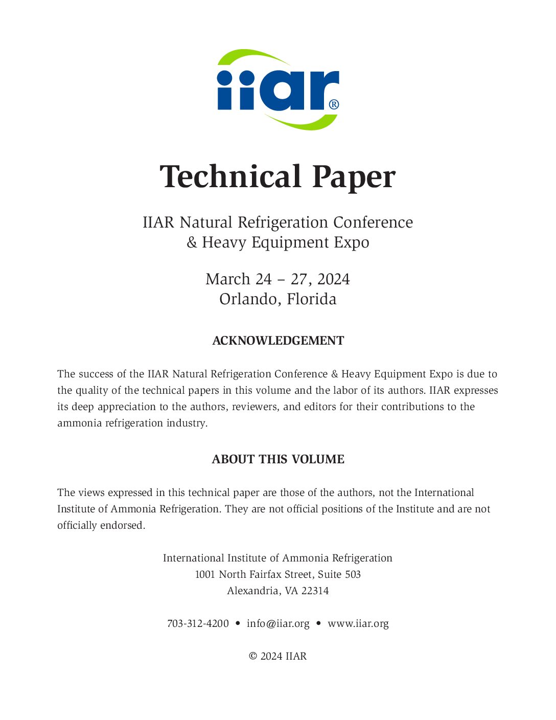
The concept of CO2 compressors with integrated intelligent modules and wired peripheral components brings various advantages to OEMs, contractors, and operators. The benefits include enhanced efficiency and reliability, as well as cost savings during installation and operation, as reported by Reichle (2019). The onboard intelligent module, along with wired accessories, as depicted in Figure 1, enables compressor centric control of the compressor functions such as capacity control, oil level management, oil pressure, discharge gas, and motor temperature. It also provides data logging and tracks the compressor’s application limits through operating envelope monitoring, ensuring safe and efficient operation across the entire application range while enhancing system safety and run-time availability. The intelligent 8-cylinder CO2 compressor can be operated effectively and reliably with a run command signal and 0–10 V capacity control from the system controller. Using this intelligent logic, the compressor capacity can be adjusted quickly to the cooling demands within a modulation range of 50%–100% of VFD operation from 30 to 60 Hz, minimizing pressure fluctuations on the suction side, preventing wet operations, and ensuring precise temperature control for products and processes. Additionally, this new concept can provide start unloading which reduces the energy consumption of the system in comparison to systems that have more basic compressor capacity control. In applications with highly fluctuating capacity requirements, such as in many industrial refrigeration settings, the intelligent 8-cylinder CO2 compressors provides great economic and technical advantages. During operation, the compressors are minimized from starting and stopping, reducing wear of the moving parts, and increasing the compressors’ service life. Using specific intelligent software, compressor operation data, counters, and statistics can be displayed graphically and listed in tabular form, making the operating concept safe, intuitive, and easy to understand.
Capacity Control System (VARISTEP) for CO2 Compressors
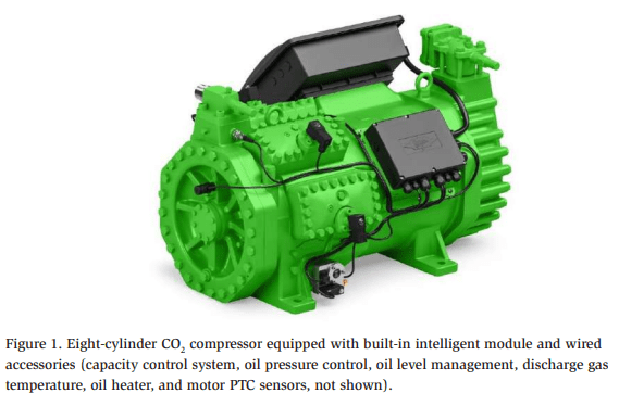
As described by Javerschek (2008), controls may be used to vary compressor capacity in a quasi-stepless manner to fulfill the high part load requirements of systems in commercial applications. The 8-cylinder models, intended for large-scale applications, are equipped with four solenoid valves for capacity regulation and start unloading. In these compressors, controls are applied to vary the capacity between 50%, 75%, and 100%. Solenoid valves are activated effectively via the compressor’s intelligent module which ensures the smoothest possible operation by providing an optimized activation sequence for the solenoid valves. This ensures efficient cooling of each cylinder head if the compressor is operated unloaded for an extended period. When the compressor operates with full load, all solenoid valves are de-energized (100% capacity). When unloading a cylinder bank, the coil is powered and high-pressure gas passes through a small channel inside the control piston and pushes the piston into a seat above the suction chamber (2). Subsequently, an internal bypass is opened and the pressure above the control piston is reduced to the suction pressure level. Consequently, the control piston is lifted and opens a bypass between the discharge (3) and the suction chamber (2) of the controlled cylinder bank, equalizing the pressure of the cylinder bank up to the check valve, as shown in Figure 2. The check valve, located on the valve plate, prevents any reverse flow from the highpressure side of the system. This capacity control system presents a cost-effective alternative, especially when compared to VFD operations, particularly in the case of large compressors like the 8-cylinder models. The data logging and operating data as well as control parameters can be monitored or read out via the intelligent module software.
CO2 Ejector Description and Operation
Compared to other refrigerants, CO2 provides considerably higher throttling losses. This characteristic, however, offers the possibility of implementing devices
like ejectors to recover expansion work. Hafner and Pardinas (2019) described that ejectors can significantly improve the energy efficiency of transcritical CO2 refrigeration or heat pump systems, especially under high ambient temperatures. To achieve high energy efficiency within a system, ejectors must operate efficiently under a variety of conditions. The ejector design has a significant impact on the system’s performance and energy consumption. Two-phase ejectors provide even better performance than traditional high-pressure control valves in reducing throttling losses and improving the overall system COP. An adjustable geometry ejector offers the flexibility to control the system’s high pressure (like HPV) and maintain high system efficiency even during part-load operations. In contrast, a fixed geometry ejector may experience a significant drop in performance under part-load conditions when the operating parameters deviate from the design specifications the ejector was originally intended for.
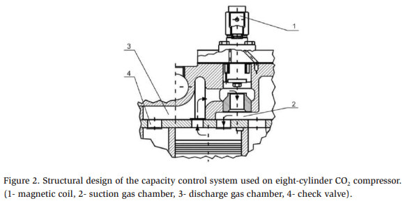
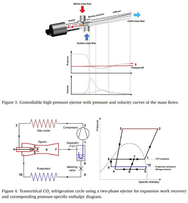
An ejector operates like a jet pump, generating a pressure below the suction level based on the Venturi principle, consisting of key components: a motive nozzle, suction nozzle, mixing chamber, and diffuser, as reported by Javerschek et al. (2022). The ejector functions by accelerating refrigerant from the high-pressure side, often leaving the condenser or gas cooler outlet, through the motive nozzle, which increases its kinetic energy while decreasing the fluid’s pressure as shown in Figure 3. The ejector harnesses the potential and kinetic energy inherent in the refrigerant from the gas cooler outlet to draw in a suction mass flow and elevate it to a higherpressure level. As depicted in Figure 4, the ejector is linked to the evaporator outlet, where it compresses the evaporated refrigerant to the flash gas tank’s pressure level. The high-pressure CO2 [2], leaving the compressor, gains velocity in the ejector nozzle [4] followed by cooling in the gas cooler [3]. This causes a drop in static pressure, resulting in the flow pressure leaving the nozzle [5/6] being lower than the evaporator’s suction gas pressure [9]. This differential pressure enables the selective extraction of both gas and liquid from a low-pressure level [9]. These partial flows merge in a mixing chamber [6] located ahead of the diffuser [7]. Within the diffuser, the flow decelerates, leading to an increase in pressure to the intermediate pressure level [7]. Beyond the diffuser, the mixture is directed into the flash gas tank, where the gas phase [1] is separated from the liquid and then compressed to a high-pressure level [2]. Meanwhile, the liquid [8] proceeds to the throttling valve and subsequently enters the evaporator [9].
CO2 Ejector Characteristic Values
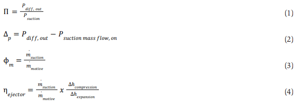
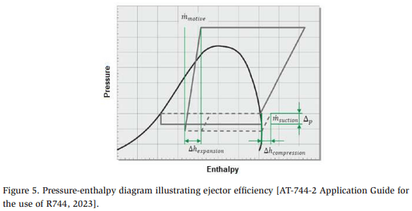
Elbel (2011) reported that various parameters are utilized to evaluate the performance of the two-phase expansion ejector. These parameters encompass the pressure ratio, pressure lift, mass entrainment ratio, and ejector efficiency. Optimal ejector performance is achieved when a significant pressure lift is combined with a high suction mass flow rate. The pressure ratio, as defined in Equation (1), represents the ratio of the ejector’s outlet pressure to its suction pressure. It quantifies the amount of pressure lift that the ejector can impart to the entrained fluid. The pressure lift, outlined in Equation (2), corresponds to the difference between the mixed stream pressure at the ejector outlet and the suction nozzle pressure, indicating the extent to which the suction mass flow pressure has been elevated to the outlet level. The mass entrainment ratio, as expressed in Equation (3), is defined as the ratio of the suction mass flow rate to the motive mass flow rate. This equation measures the ejector’s capacity to entrain or pump refrigerant mass. The ejector efficiency, presented in Equation (4) and defined in Figure 5, is the ratio of the energy gained by expanding the ejector’s motive mass flow to the work performed by the pressure lift of the motive mass flow and the suction mass flow at the ejector outlet. These calculations assume isentropic expansion and compression, along with superheated and dry saturated vapor conditions.
Simon et al. (2022) reported that, depending on the operating conditions, mass flow through the motive nozzle may be limited by choking, and a converging-diverging nozzle can even accelerate the refrigerant to supersonic speeds. If the pressure at the motive nozzle exit is lower than the suction pressure, it induces a secondary flow of refrigerant, typically from the evaporator, drawn in through the suction nozzle. The secondary mass flow might also be limited by choking. These primary and secondary flows combine in the mixing chamber, often generating shockwaves and causing an instantaneous pressure increase. At the diffuser, the kinetic energy of the refrigerant mixture transforms into potential energy, raising the pressure. The ejector’s outlet pressure then falls between the pressures at the motive and suction nozzle inlets. Two critical features of the ejector are the pressure hub, which is the pressure difference between the ejector outlet and the suction nozzle inlet, and the mass entrainment ratio, described as the ratio of suction nozzle mass flow compared to motive nozzle mass flow. The ideal ejector maintains a high-pressure hub and a high entrainment ratio for optimal performance.
Ejectors for Low and High Lift Applications
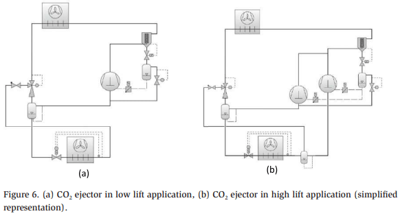
In low lift applications, ejectors aim to achieve the maximum possible mass flow. Their primary role is typically to recover the entire evaporated mass flow within the system and return it to the intermediate pressure vessel as shown in Figure 6 (a). In this application, the MT compressor operates as a parallel compressor controlling the intermediate pressure vessel, which is higher than the MT evaporator pressure. The critical factor in this context is the mass flow itself, which dictates the ejector’s capability to boost pressure or determine the upper limit for intermediate pressure, allowing for efficient refrigerant return. The flash gas tank serves to separate the liquid and gas phases. The gas phase is drawn by the compressor, constituting the motive mass flow. Meanwhile, the liquid phase remains accessible to supply the evaporator and constitutes the suction mass flow. Ejectors in low lift applications function as robust “refrigerant pumps” with the ability to handle gas-liquid mixtures. This capability facilitates operations with flooded evaporators, eliminating the need for a superheat section and enabling higher evaporating temperatures without risking harm to the compressor.
In high-lift applications, ejectors are employed to achieve the maximum possible pressure increase while maintaining a reduced delivery rate. As depicted in Figure 6 (b), the ejector is used to load the parallel compressor and unload the MT compressor. Not necessarily the entire suction mass flow must be taken in. Depending on the medium pressure level and the resulting entrainment, the ejector elevates the pressure of a portion of the suction mass flow. This scenario requires a delicate balance between pressure lift and the desired suction mass flow, aiming to optimize system efficiency. Ejectors in high lift applications are typically used for transporting superheated gas only, as they do not handle the entire evaporated mass flow. In addition, a portion of the mass flow continues to be extracted by medium-temperature compressors. The ejector transports this portion of the mass flow back to the intermediate pressure vessel, which is maintained at a higherpressure level compared to low lift configurations. The gas is now extracted from the intermediate pressure vessel by the parallel compressor. The advantage of this setup lies in the pre-compression of a portion of the evaporated refrigerant, resulting in a load redistribution to the parallel compressor, which operates at a lower pressure ratio, leading to increased overall efficiency. In a semi-flooded system, a separator, also known as a suction accumulator, is employed to allow the operation of MT evaporators with minimal superheat. In this scenario, the ejector functions as a liquid ejector, directing the surplus liquid from the MT evaporators/suction accumulator back into the flash gas tank. An oil return line must be installed to return the oil to the compressor from the suction accumulator.
Ejector Control Characteristics
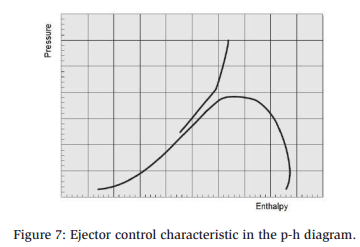
High pressure is optimized by the ejector’s control characteristic as shown in the Figure 7. This is accomplished through a control characteristic determined by the manufacturer of the system controller. A control characteristic is used to compare the measured high pressure and temperature at the gas cooler outlet with the target high pressure. The system controller generates an analog control signal based on the control deviation between the measured high pressure and the target high pressure. As a result of this signal, the ejector’s stepper valve is actuated, changing the crosssectional area of the ejector’s nozzle, which affects the mass entrainment ratio and the high pressure. This relationship needs to be considered when planning and designing systems for low lift/liquid ejectors to avoid stall effects, especially at low pressures.
Depending on the ejector application there may be different operating conditions, such as an open or closed suction line. These conditions are activated by factors such as the gas cooler outlet temperature and motive mass flow inlet temperature. In some cases, however, relying solely on the gas cooler outlet temperature may not provide sufficient information about the cooling points’ load requirements. Additional criteria may be factored in based on the manufacturer and type of system controller. Among the variables that can be analyzed are the opening degree of the flash gas bypass valve, the opening degree of the high-pressure control valve, the operation feedback from the compressors, and the alarm messages.
Ejectors for Industrial Large-Scale Transcritical CO2 Systems
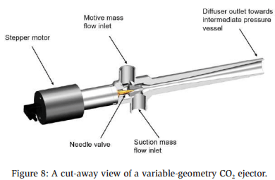
CO2 ejectors can provide the most significant energy efficiency gains in high ambient temperatures by reducing compressor power consumption while minimizing system platform complexities. CO2 ejectors with variable geometry offer a nominal mass flow range spanning from 1764 lb/h to 20.948 lb/h (800 kg/h to 9500 kg/h) at inlet conditions of 87.8°F (31°C) and 1334 psia (92 bara). The largest ejector used here delivers 977 kBTU/h (286,4 kW), making it compatible with the 8-cylinder CO2 compressor designed for large-scale applications. These ejectors effectively manage mass flow through their motive nozzles using a needle valve, enabling precise control of the transcritical pressure at the gas cooler outlet. They offer accurate regulation of the gas cooler’s optimal discharge pressure across a broad range of applications, effectively replacing high-pressure valves. Closing the needle valve reduces the motive nozzle throat area. The needle valve’s position, controlled by a stepper motor, is referred to as “utilization,” where 100% utilization corresponds to a fully open needle valve. It is possible to employ a combination of different sized ejectors to achieve additional improvements in the system’s COP, enhancing performance not only at full load but also at part load conditions. Figure 8 shows A cut-away view of a variable-geometry CO2 ejector.
Energy Efficiency Analysis: CO2 Refrigeration System with Eightcylinder Compressors and Ejectors in Grocery Distribution Center
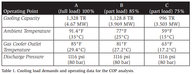
The analysis was conducted using Bitzer CO2 system software version 7.0 to compare 8-cylinder compressors with ejectors to existing 4- and 6-cylinder compressors without ejectors in operation at a grocery distribution center in Maryland. The facility features one of the world’s largest CO2 refrigeration systems, with a cooling capacity of 1,328 TR (4.67 MW). This capacity includes 1,022 TR (3.87 MW) for medium temperature (MT) applications at 21°F (-6.2°C) SST and 227.5 TR (0.8 MW) for low temperature (LT) applications at -21°F (-29.44°C).
The distribution center houses five transcritical CO2 refrigeration racks employing parallel compression technology. These racks incorporate 57 compressors with 4- and 6-cylinder configurations. In this facility, each rack operates independently, with loads distributed among them so that each refrigerated space has a backup. The existing CO2 racks are designed with adiabatic gas coolers to maintain the gas cooler outlet temperature at 85°F (29.4°C) during the summer.
The analysis refers to the existing CO2 flash gas system with parallel compression as the FGP system, and the system with 8-cylinder CO2 compressors and ejectors, as an FGE system. Based on the parameters outlined in Table 1, the COP is examined for both full- and part-load operations. Assuming the adiabatic gas coolers maintain the outlet temperature at 85°F (29.4°C) at point A (highest ambient temperature), and at points B and C the temperature difference between the gas cooler outlet and ambient temperature is targeted to be 4°R (2.2K). The superheat of the evaporator and the suction line for all systems was set at 9°R (5K), and to prevent wet operations, internal heat exchangers (IHXs) were incorporated in all systems. Additionally, desuperheaters were installed on the compressor discharge lines for the lowtemperature stage (LT-stage) to prevent high suction gas superheat on the mediumtemperature stage (MT-stage). The discharge pressure was maintained at 1116 psi (80 bar) at all three operating points to optimize the ejector efficiency. A heat recovery of 455 TR (1.6 MW) was assumed for various purposes such as domestic hot water, space heating, warming glycol for under-slab radiant heating, and hot water used in washdowns. A simplified diagram of the FGE and FGP system is shown in Figure 9.
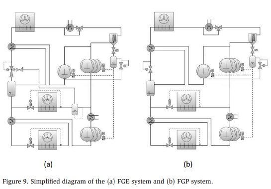
The intermediate pressure of these systems is optimized to achieve the highest coefficient of performance while utilizing the minimum number of compressors across operating points. At full load operation (operating point A), the FGE system requires five 6PME-40K compressors for the LT-stage, six 8-cilynder compressors for the MT-stage, ten additional 8-cylinder compressors for the parallel-stage, and eighteen ejectors. The FGE system’s lead compressor in each suction group utilizes capacity regulation to adapt to the required mass flow. The FGE system employs 21 compressors, which is a significant reduction compared to the 57 compressors utilized in the existing FGP system. Figure 10 illustrates the COP comparison between the FGB and FGE systems under full- and part-load conditions.
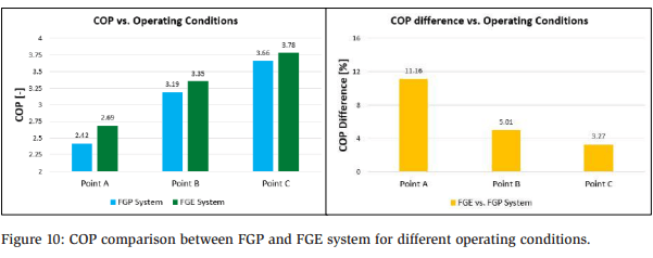
The FGE system demonstrated a significant improvement in COP of 11.16% at point A, followed by improvements of 5.01% and 3.27% at points B and C, respectively, compared to the existing FGP system. The ejectors, particularly at point A, played a pivotal role in moving most of refrigerant mass flow between the MT evaporators and parallel compressors, contributing to the highest COP at that specific operating point.
Eckert et al. (2022) reported that while ejectors perform well under original design conditions, when deviations from these design conditions occur, ejector efficiency drops, resulting in a decrease in overall system efficiency. Under subcritical conditions, the ejector may operate with lower motive pressure and reduce the energy content of the refrigerant flow.
Analysis by Simon et al. (2022) on the COP of three different CO2 systems designed for a central European distribution center, considered various operating conditions. These systems, all incorporating 8-cylinder CO2 compressors, were configured with flash gas bypass (FGB system), parallel compressors (FGP system), and ejectors (FGE system). Their research revealed that the FGE system outperformed both the FGB and FGP systems, delivering a superior COP. The researchers underscored the importance of considering both full load and part load conditions when designing a CO2 refrigeration system with ejectors. They highlighted that at higher ambient temperatures, the ejector input pressure and energy increase, leading to greater energy benefits and a higher COP. Conversely, lower ambient temperatures result in reduced energy benefits due to the decreased potential energy available to the ejector.
Conclusion
In recent years, there has been a notable shift in the adoption of transcritical CO2 racks from traditional supermarket settings to the industrial sector. This paper highlights the potential of intelligent 8-cylinder CO2 compressors and ejectors as highly efficient solutions for industrial applications. The growing capacity and adaptability of these technologies render them viable for diverse applications, providing advantages such as heightened efficiency, decreased energy consumption, reduced space requirements, low operating costs, and enhanced safety.
The energy efficiency analysis in this paper reveals that 8-cylinder CO2 compressors and ejectors allow for a reduction in the number of compressors in large systems. In this study, the FGE system employs 21 compressors + 18 ejectors instead of 57 compressors without ejectors in the existing FGP system. The improved EER/COP is a result of better performance provided by the 8-cylinder CO2 compressors, with ejector operation playing a major role in that improvement.
Intelligent 8-cylinder CO2 compressors and ejectors are positioned not as competitors, but as sustainable alternatives to ammonia-based systems in industrial applications. By integrating these technologies, CO2 systems operate efficiently in transcritical mode, resulting in a substantial increase in the COP especially in warm climates. This breakthrough addresses the historical challenge of CO2 systems struggling to operate efficiently in higher ambient temperatures.
The removal of this efficiency barrier opens up possibilities for installing CO2 systems for commercial and large-scale industrial applications worldwide. The versatility and performance enhancements brought by intelligent 8-cylinder CO2 compressors and ejectors make transcritical CO2 systems a viable and efficient choice.
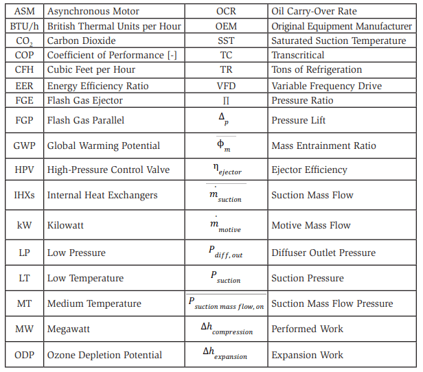
Nomenclature
References
Silva, A., Sanchez, J. 2022. Oil Management Design Considerations for Industrial Transcritical CO2 Systems. IIAR Natural Refrigeration Conference & Expo, Savannah Convention Center in Savannah, Georgia from March 6–9, 2022. Technical Paper #5.
Javerschek, O. Mannewitz, J., 2021. Advanced Design for CO2 Compressors in Industrial Applications. 9th IIR Conference on Ammonia and CO2 Refrigeration Technologies, Ohrid, North Macedonia, 16-17 September, 2021. http://dx.doi.org/10.18462/iir.nh3-co2.2021.0009
Reichle, M. 2019. Mastering the Technology of Transcritical CO2 Applications. International Refrigeration Seminar, BITZER SCHAUFLER Academy, RottenburgErgenzingen, June 2019.
Javerschek, O. 2008. Commercial Refrigeration Systems with CO2 as Refrigerant. 8th IIR Gustav Lorentzen Conference on Natural Working Fluids, Copenhagen. http:// www.ammonia21.com/files/pdf_760.pdf
Hafner, A., Pardinas, A. 2019 refrigeration technology: Possible Innovations. 8th IIR Conference: Ammonia and CO2 Refrigeration Technologies, Ohrid, 2019. http://dx.doi.org/10.18462/iir.nh3-co2.2019.0024
Javerschek, O., Mannewitz, J., Hegglin, A. 2022. The use of ejectors in industrial heat pumps. 15th IIR-Gustav Lorentzen conference on Natural Refrigerants, Trondheim, Norway. DOI: 10.18462/iir.gl2022.070
Elbel, S. 2011. Historical and present developments of ejector refrigeration systems with emphasis on transcritical carbon dioxide air-conditioning applications. International Journal of Refrigeration, 34(7), pp.1545-1561.
Simon, F., Pfaffl, J., and Javerschek, O. 2022. Introduction of an Ejector for Industrial Scale CO2 Systems. International Refrigeration and Air Conditioning Conference. Paper 2493. https://docs.lib.purdue.edu/iracc/2493
Eckert, M., Kauffeld, M. and Siegismund, V. 2022. Natural refrigerants: Applications and Practical Guidelines. 2022 VDE VERLAG GMBH and Shecco SPRL (ATMOsphere).
ATMO Report, 2023. Natural Refrigerants: State of the Industry. Refrigeration in Europe, North America and Japan, Plus Heat Pumps in Europe. 2023 Edition. https://atmosphere.cool/atmo-market-report-2023/
Lorentzen, G., Pettersen, J. 1992. New possibilities for non-CFC refrigeration. IIR Int. Symp. on Refrigeration, Energy and Environment, Trondheim, Norway, June 22-24, pp.147-163.
BITZER AT-744-2 Application Guide for the use of R744, 2023. https://www.bitzer.de/shared_media/html/at-744/en-GB/index.html?P=/html/at-744/en-GB&N=index.html BITZER CO2 Software version 7.0 [Computer software], accessed on Dec 4th, 2023. https://www.bitzer.de/websoftware/calculate/CO2/?tab=results
Coolsys, 2023. https://coolsys.com/ [Coolsys webpage], accessed on Sep 22nd, 2023.
Acknowledgements
- Oliver Javerschek and Manuel Reichle, Application Engineers, BITZER Kühlmaschinenbau GmbH
- Miguel Boscan, Application Engineering Manager, BITZER US.
- Scott Hanson, Application Engineering, BITZER US.