2025 Technical Paper #6
Refrigeration System Design Using Float Expansion Valves
Author: Todd B. Jekel, PhD, PE, Assistant Director, Industrial Refrigeration Consortium, University of Wisconsin-Madison
Abstract
Large industrial refrigeration systems often suffer from operating instabilities caused by refrigerantliquid feed controls that are poorly engineered or improperly tuned. A strategy that requires more sophisticated controls potentially addresses operating instabilities but may introduce other challenges that can further destabilize system operation. The use of float expansion devices is proposed as a simple but effective means of achieving stable system operation. This paper provides further details on design considerations for float expansion devices incorporated into large industrial ammonia refrigeration systems. Details on refrigeration system configuration, equipment sizing, conceptional advantages, and disadvantages are considered for the range of temperature requirements for food manufacturing and cold storage warehousing facilities.
Introduction
Mechanically pumped liquid overfeed systems continue to see application throughout the industrial refrigeration industry. This system configuration requires a liquid containing vessel as a reservoir for the liquid refrigerant pump to reliably deliver liquid to the attached evaporators (Yencho, 1989, 2005). The current state-of-the-art refrigeration system for the recirculator vessel’s liquid level control relies heavily on an electronically modulated expansion valve coupled with a continuous level sensor fitted into a level column. The use of the modulating expansion valve smooths out the on/off characteristic of the liquid makeup of traditional solenoid paired with a manually set hand expansion valve. Liquid makeup for vessel level control results in flash vapor formation as the liquid is throttled from the higher pressure. This results in a suction vapor flow rate that the compressors must process. The on/off nature of a solenoid and a hand expansion valve results in a step change in the suction vapor volume flow rate every time the vessel’s level sensor “calls” for liquid makeup. Depending on the setting of the hand expansion valve, this process results in suction pressure fluctuations and, in extreme cases, triggers the starting of another compressor to maintain the system’s suction pressure. Continuous vessel level sensing coupled with a modulating expansion valve, theoretically, should reduce the compressor hunting associated with an on/off vessel level control; however, in practice this ends up being more difficult to implement and in certain circumstances could be worse than on/off level control.
The reasons for system control instability due to vessel liquid level control are numerous and can be rooted in both design and operations. First, ideally, the vessel’s liquid level change would be an indication of the load on the portion of the refrigeration system served by that vessel so that the makeup liquid amount (and resulting flash gas from the throttling to the lower pressure) is proportional to the load. Unfortunately, there are level changes that are not simply a function of the load. Fluctuations in return of overfed liquid to the vessel due to wet-suction return piping (e.g., improperly sized vertical riser(s) or inadequate pitch on horizontal return piping), pump out (or pump down) of refrigerant in evaporators prior to hotgas defrost, and refill/rechill of evaporators after defrost are all situations where the liquid refrigerant level in the recirculator vessel changes independently of the instantaneous refrigeration load.
Depending on the magnitude of these “non-load” factors and their connection to the actual refrigeration load on that part of the system, the effect on the vessel level and subsequent control programming of both the vessel level control and compressor sequencing can be result in deviations from the desired operating points of liquid level and suction pressure. The compressor control is an issue because the mass flow rate required for suction pressure control is the sum of both the vapor mass flow rate from the evaporators (i.e., the load) and also the flash vapor mass flow rate from the liquid makeup for vessel level control; therefore, liquid makeup control is critical for system stability.
Second, the chosen level control methodology’s dead-band and other parameters, vessel orientation and size, makeup liquid state point, and expansion valve sizing can further complicate the ability for the control system to find and maintain a stable operating point. Large diameter vessels (especially horizontal vessels) will experience large volume changes in liquid refrigerant inventory relative to the dead band. Further, the continuous level sensing technology must be able to either sense small level changes or be programmed in such a way to allow a wider range of permissible vessel liquid level to be stable. The control architecture can also influence stability. One common level control methodology for maintaining a vessel’s liquid level increases the makeup valve’s open fraction by some percentage on a recurring time step.
For example, if the vessel level is below the set point the modulating expansion valve is opened a fraction (input parameter). A time step (input parameter) later, say 1 second, if the level is still below the set point, the modulating valve’s open fraction is increased (input parameter). This process is continued until the vessel level is at the set point. In order for this control concept to be stable, the parameters must consider the time lag between the increased makeup mass flow rate and its resulting liquid level change in the level column and the level sensing technology’s sensitivity. User input of a time step parameter that is shorter than the response to the increased makeup mass flow rate will result in the modulating expansion valve overshooting and undershooting the level set point and coupled with the delays on the compressor loading and unloading create suction pressure fluctuation and can result in effectively on/off control despite having an expansion valve with flow modulating capability.
Finally, operational settings can exacerbate the problem. Overfed system require attention to detail from both the designer and operations staff (although this is true of ALL systems). The setting of hand expansion valves used to meter in the required mass flow rate for the evaporator during refrigeration mode is important. Too much mass flow to the evaporator (i.e., too high overfeed rates) can result in larger transients in vessel level and, for evaporators requiring a vertical suction riser (i.e., evaporators below roof-mounted suction mains), can further create the possibility of a larger difference due to improperly sized riser piping that doesn’t consistently lift the overfed liquid to the suction main.
Some practitioners point to these reasons as disqualifying for the use of an overfed system. Although this argument might be compelling for some, the reality is that all systems are subject to similar control issues – not just overfed systems. Properly designed, installed, and operated systems of any type can be successful.
Low Charge System Design
Current industry trends using direct expansion evaporators fed with subcooled highpressure liquid and the use of high-pressure liquid for compressor oil cooling (either liquid injection or thermosiphon) commonly use a vessel that stores and delivers high-pressure liquid refrigerant. There has been some industry attention paid to reducing the required operating charge (i.e., mass) of refrigerant in the systems; however, achieving the objective of a reduced refrigerant charge has largely focused on moving from overfed to direct expansion evaporators or to secondary fluids. Systems designed using direct expansion evaporators can result in an overall larger system volume compared to an overfed system. An increased system volume may result in increased charging of the system (i.e., increased operational liquid level in the high-pressure receiver, or HPR) as failures in evaporator liquid feed control or challenges of free draining condensers during cold weather operation occur.
Fundamental charge reduction of a refrigeration system is accomplished by a reduction in system volume. Many assertions regarding the charge of overfed systems highlight the high evaporator charge for poorly set up evaporators (i.e., hand expansion valve setting), especially when the evaporator requires a vertical suction riser to a roof mounted suction return main but rarely mention the failures that can exist with the direct expansion evaporators. The design (i.e., sizing) of the riser can also be a contributor to increased overfed evaporator charge if the installed piping does not have enough vapor velocity to consistently lift the overfed liquid to the suction main. Both issues can be remedied.
A refrigeration system design that eliminates the requirement of high-pressure liquid and therefore the high-pressure receiver (i.e., storage vessel) can decrease the system operating charge AND reduce the rate at which the refrigerant will leave the system if a leak occurs due to the storage of refrigerant at a lower pressure. To do this, the refrigeration system configuration, the design rules used for vessel sizing, and the method of compressor oil cooling will necessarily be changed. The easiest way to accomplish the change is to use mechanical pumps to deliver liquid refrigerant to the evaporators. Historically, a controlled pressure receiver, coupled with a liquid transfer system, was used (Klysen and Ross, 2007). This controlled pressure receiver configuration can still be used (and may be required in certain circumstances); however, the transfer system, regardless of type, is a complication that adds operating complexity, risk, and cost making it less appealing to many owners.
Eliminating the Need for High-pressure Liquid in System Design
There are three (3) design approaches that can be used to eliminate the need for high-pressure liquid refrigerant in refrigeration systems: 1) high-side float drain the condensers (preferably drain each condenser tube bundle to eliminate the use of gravity to drain liquid from the condensers) to a lower pressure vessel, 2) mechanically pump liquid to the evaporators, and 3) use of glycol-cooled oil coolers coupled with a fluid cooler and heat recovery (if needed). The first item is addressed in this paper.
The lack of a high-pressure vessel is uncommon in most refrigeration system designs; however, once the need for high-pressure liquid is removed, there is no need for a vessel to store high pressure liquid, rather, all liquid refrigerant is stored on the low side of the system. The author has seen multiple systems with small high-pressure vessels (used for supplying thermosiphon oil coolers only) and a smaller number of systems with no high-pressure receiver (HPR) (reciprocating compressors with water cooled heads).
Delivery of liquid refrigerant to remote evaporators fundamentally requires a pressure difference. Using the pressure difference inherent to the mechanical vapor compressor refrigeration cycle is the most direct way of moving liquid; however, to reliably deliver saturated liquid over a pressure difference without causing problems with respect to the flashing of vapor, the high-pressure liquid must be subcooled. While using the inherent pressure difference created by the refrigeration cycle might be convenient, the availability of centrifugal liquid refrigerant pumps as an alternative to create the pressure difference for liquid delivery to evaporators offers several advantages: 1) pressure difference independent of the high-side pressure thus allowing for lower condensing pressure operation, and 2) simple evaporator liquid feed valve trains that, when coupled with evaporators installed in penthouses, allows for the complete removal of potential leak sites from inside the refrigerated space and the elimination of any significant rise to roof mounted suction mains.
It is also important to realize there are disadvantages to liquid refrigerant pumps as well: 1) they don’t work as well with evaporators that require pressure regulators, and 2) there is added capital cost associated with the pump(s) and the associated piping, valves, and controls. A subtle addition to the listing of advantages and disadvantages is the specification of penthouses for the evaporators. This is obviously not without cost; however, there are benefits that offset those costs that facility operation staff value over the life of the system and should be considered in any refrigeration system design.
Float Devices
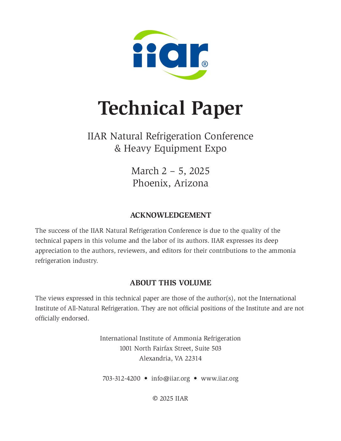
The expansion device used between pressure levels is a high-side float shown in Figure 1. A high-side float is a simple device that uses a ball () that is lifted by the presence of liquid and a linkage uncovers the port () to allow expansion of the liquid to the lower downstream pressure. These devices are not new to the industry. The advantage of a system design using floats is a reduction of required sensors used for control (e.g., liquid level sensing, refrigerant superheat [pressure and temperature or quality]) and associated control programming along with the ongoing sensor calibration required to maintain system function.
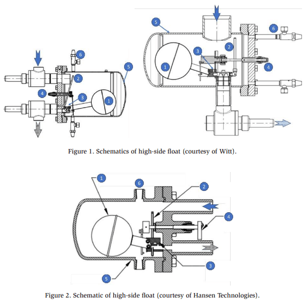
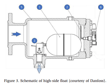
Figures 1-3 shows the details of several valve designs. For each model shown, isolation valves, a manual opening actuator (if exists), and two () small valves on the body (or bell) of the valve can be used for maintenance or external vapor equalization . Every float has a small vapor bypass ② internal to the valve to avoid vapor binding; however, this feature becomes flaw when there is no liquid in the body (i.e., the float ball is down). While vapor binding can be an issue, the use of an external equalization guards against vapor binding and doesn’t create a hot gas bypass penalty during low load operation. Some float models have the liquid enter the body from the top thereby virtually eliminating the possibility of vapor binding; however, the bypass still exists in those valves. That said, there are instances when he bypass is necessary such as when the float is installed above the liquid level, for instance, when used to drain liquid out of a ceiling hung evaporator during defrost.
The bypass can be plugged in consultation with the manufacturer
A float is an expansion device; therefore, its capacity will be affected by the flash vapor that is formed as the saturated liquid refrigerant expands through the float’s port. The amount of flash vapor formed downstream of the port is a function of the upstream and downstream pressures. The performance of any valve (including a float) with flow conditions that result in some of the liquid flashing to vapor is a complicated subject. Some manufacturers have computer selection programs to aid the designer in the selection of the float and these should be used for valve specification if available.
Refrigeration System Configurations Using Float Expansion
The configuration of the refrigeration systems to accommodate the wide range of refrigeration requirements in industrial refrigeration can be complicated. It is no different when using floats for expansion. Throughout this section a vessel and pipe service naming abbreviations will be used without introduction at the first occurrence. The abbreviations are listed at the end of the paper.
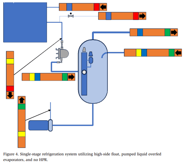
The simplest industrial refrigeration system with float controls is a single stage compression with a single temperature requirement (i.e., a single suction level) with the liquid expansion through the float as shown in Figure 4. The evaporators are configured as liquid overfeed using a mechanical pump attached to a medium pressure recirculator (MPR). Any oil or head cooling required by the compressors would need to be external, usually supplied using glycol with a fluid cooler to reject any heat that wasn’t able to be recovered and used by the facility (Reindl and Jekel, 2007). Note that while the level column on the recirculator is shown with a representation of a continuous level sensor, the actual liquid level in the MPR is not controlled but varies as the load on the system varies. The sensor output is for communication of the MPR liquid level to operations staff only and used primarily for determining when the system would require additional refrigerant. The level column is also fitted with a high level mechanical float to cut out compressors in the event of a high level; however, the size of the vessel needs to be able to hold the system charge below that level thereby making it impossible to have a high level event unless the system was overcharged or expanded past it storage volume. Note also there is no external equalizer piping on the float because the float shown drains liquid into the top of the body thereby eliminating the possibility of vapor binding. The internal bypass (i.e., low-pressure nozzle or capillary tube) in the float should be blocked (see in Figures 1-3).
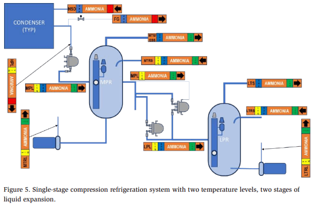
An extension of the single-stage compression system with float controls is a system with refrigeration loads at two different temperatures (i.e., two temperature levels or two suction pressures). Figure 5 shows such a system with the higher temperature loads being served by either compressors or the side-port on the low-temperature rotary screw compressors. Liquid is expanded to the low-temperature recirculator vessel through the medium-temperature recirculator vessel (i.e., two stages of liquid expansion). Evaporator liquid feed and any compressor oil or head cooling are handled externally to the system as previously noted. Note that there are multiple floats (a float “tree”) on the MPR feeding liquid to the LPR to accommodate a range of low-stage system loads and the highest installed float is externally equalized, as such, all other floats on the float tree have the internal bypass blocked. The LPR is the uncontrolled level vessel in Figure 5.
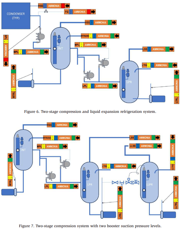
Extension of the single-stage compression, two temperature level, two-stage of liquid expansion shown in Figure 5 is a system with two-stage compression as is shown in Figure 6. The intercooling (not shown) can be accomplished either directly (i.e., flash) or indirectly (i.e., directing pumped liquid into the BD/MTRS from the MTRL).
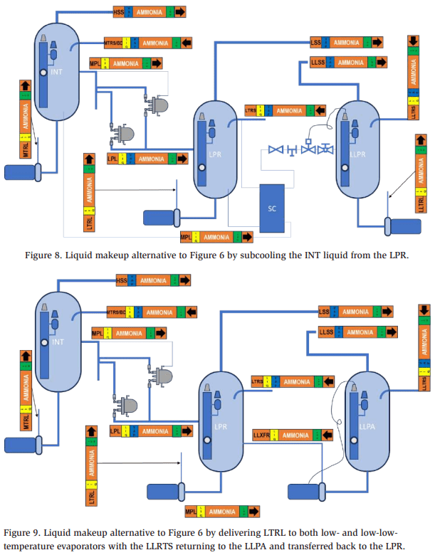
When the facility requires more than two temperature levels, the system design will necessarily be more complicated. The use of floats requires a single expansion “float path” from the highest to lowest pressure vessel As such, system configurations with multiple vessels attached to the same pressure (temperature) level (e.g., a system with two LPRs) or vessels that have small pressure differences between them (e.g., a system that has a low- and a low-low-pressure recirculator for low-stage loads) requires more creativity. Figure 7 shows the extension of the two-stage compression system introduced in Figure 6 to three-temperature levels, and three-stages of liquid expansion using the LTRL to provide liquid makeup to the LLPR. While the third stage of liquid expansion provides little effect and would likely not be done with more traditional level control and makeup valve trains, the use of the float from the INT to the LPR requires that all the mass flow runs through the LPR. Parallel floats from the INT to the LPR and LLPR would not work and the use of a solenoid downstream of the floats is both not recommended and would negate the benefit of the float control. Due to the small pressure difference between the LPR and LLPR, the low-temperature mechanical pump discharge is used to make up the LLPR and is level controlled by a continuous level sensor and a motorized expansion valve. Care must be taken when specifying the pump to account for the liquid make up to the LLPR and the sizing of the liquid makeup valve train to the LLPR because the liquid state point (i.e., subcooled) will have very little flash vapor formed during the expansion and a smaller sized makeup valve train is required and oversizing control valves can create problems. Note that any vessel in parallel (i.e., same pressure level, for example a second LPR on the same suction level) to a vessel in the “float path” from high to low pressure would need to be level controlled as shown in Figure 7 for the LLPR. The uncontrolled level vessel is the LPR in both Figure 6 and 7. Figures 8 and 9 illustrate a couple of alternatives to liquid makeup from the LPR pump discharge shown in Figure 7. The alternative in Figure 8 subcools INT liquid with liquid from the LPR and a traditional liquid makeup valve train controlled on LLPR level. Note that this only has two stages of liquid expansion compared to the three in Figure 7 for a modest decrease in system efficiency. The alternative in Figure 9 delivers LTRL pumped liquid to both the low- and low-low-temperature evaporators with the overfed liquid from the low-low-temperature evaporators returned to the LLPR and then pumped back to the LPR. Note this configuration retains the three stages of liquid expansion in Figure 7.
As Figures 7-9 show, as the refrigeration system gets more complicated, so do the designs; however, this is also true for the more common liquid makeup valve trains as well.
Sizing of Float Devices
Faust (2022) recommends an approach to calculate mass flow rates throughout the system that would be used to size and specify float devices. Calculating mass flow rates becomes increasingly important as the system complexity increases (e.g., Figures 7-9). See also Yencho (2013) for information on sizing float valves.
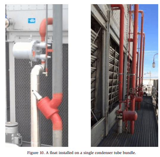
The sizing of the float device when applied to a single condenser tube bundle (Figure 10) is relatively straightforward and some piping details will be shown in the next section. The mass flow rate corresponding to the condensing capacity for the peak system load at the lowest expected condensing pressure will be the design basis. Multiple condenser tube bundles on a single float require more attention to the piping due to the reliance on gravity draining the heat exchangers. The piping resembles the more traditional condenser/high pressure receiver (HPR) piping in a sewer flow arrangement (i.e., condensers drain to the top of the HPR) with a p-trap on each condenser tube bundle drain (see IIAR Ammonia Refrigeration Piping Handbook). A float for each condenser tube bundle is the preferred arrangement (note that this means there is NO high-pressure liquid available).
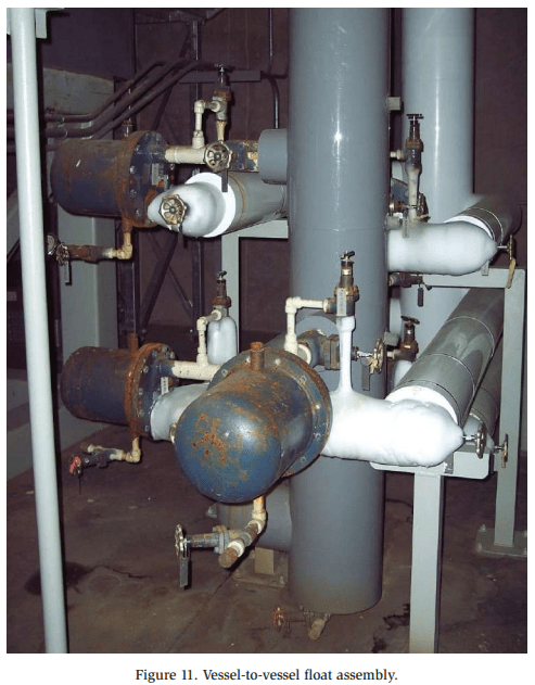
For vessel-to-vessel applications, multiple float devices are recommended for both redundancy and maintenance, but also for the range of expected refrigeration loads. Figure 11 shows a multiple float assembly for a vessel-to-vessel application. Consider splitting the peak refrigeration load (or alternatively the attached compressor capacity) into 50%, 33%, and 25% (or fractions that make sense for the specific system details) to allow for both a factor of safety and the ability to meet most (58- 83% of peak with the example) of the loads with only two (2) of the three (3) floats to allow for maintenance of one of the floats. Details on the piping will be shown in the next section.
Piping Details
Condenser to vessel
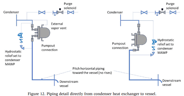
Direct application of the float to each condenser heat exchanger drain leg provides the most benefits. Figure 12 (see also IIAR, 2019 and Yencho, 2005) shows the piping detail including the purge point and the overpressure protection for a non-ASME stamped condenser using a pressure regulator and a check valve. It is preferable to close the capillary tube inside of the float and externally vent the vapor space to avoid hot-gas bypass at low load conditions. The location of the liquid entrance to the float design may eliminate the need for externally venting the vapor space (Figure 12 right schematic). Piping downstream of the float must be insulated, sized for the expected two-phase flow and oriented to drain to the downstream vessel. Vertical piping rises to the downstream vessel are not recommended from condensers..
If a high-pressure receiver is used for delivering high-pressure liquid to compressor oil cooling, or loads, the piping from the condenser will be the standard sewer flow or surge arrangement (IIAR, 2019).
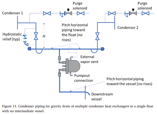
Even without an HPR vessel, if multiple condenser heat exchangers are drained by a single float, the piping is identical to a traditional gravity drain arrangement as shown in Figure 13 (see also IIAR, 2019). This typical piping arrangement uses gravity to drain from the condenser to the high-pressure receiver and is more prone to holding up liquid in the condenser during cold weather operation than individually draining each condenser tube bundle as shown in Figure 12.
Vessel-to-Vessel
Vessel-to-vessel float connections are shown in Figure 14. The schematic shows the use of multiple floats on connection that establishes the level in the upstream vessel. Multiple floats are required for larger systems; however, even a small system will benefit from multiple floats to accommodate maintenance of the floats. Unlike the condenser to vessel connection, vertical rises will often be required given that the vessels are often installed on the same grade. A rise of piping is for all intents and purposes a suction riser, and designers should be specifying the riser diameter to lift liquid. The limit for lifting liquid is a Kutateladze (KuG) number of 3.2 (IIAR, 2019) as given by Eq. 1
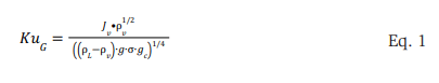
where all properties are at the downstream condition, Jv is the superficial vapor velocity (vapor flow divided by the piping cross-sectional area) in ft/s, ρv is the vapor density, ρL is the liquid density (both in lbm/ft3 ), σ is the surface tension in lbf /ft, g is the acceleration due to gravity in ft/s2 , and gc is 32.17 lbm-ft/s2 -lbf . The connection to the downstream vessel should be above the expected range of liquid levels. The uppermost float on the float tree should be externally equalized to the vessel connection on the upstream vessel. All floats should have the capillary tube closed. The connection for the float tree should be a minimum of 3″ NPS to allow for any vapor in the floats or generated by heat gain to flow back to the vessel without interrupting liquid flow to the floats.
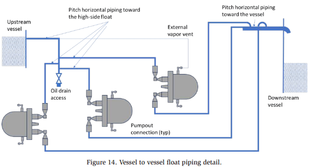
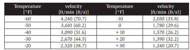
While individual risers to the downstream vessel may not be required, it does make it more straightforward to size the piping and guarantees lifting liquid under lower load conditions for each float and reduces the possibility of interruption of liquid makeup to the downstream vessel. The velocity to lift liquid is only a function of the downstream properties; however, the amount of flash vapor is a function of both the upstream and downstream properties. Table 1 shows the vapor velocity to lift liquid for anhydrous ammonia (i.e., KuG). Pipe sizes should be chosen that result in a vapor velocity higher than that in the table. The velocity, Jv, in ft/s is calculated as shown in Eq. 2
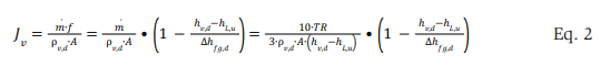
where is the total mass flow rate in lbm/s, A is the cross-sectional area of the riser piping in ft2 , TR is the refrigeration load in tons, h are enthalpies and Δhfg is the heat of vaporization in Btu/lbm with subscripts u is at the upstream condition, d is at the downstream condition, v is for vapor, and L is for liquid. Rearranging Eq. 2 in terms of piping inner diameter, d, in inches gives you Eq. 3 below
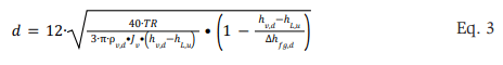
where Jv is taken from Table 1 in ft/s.
Table 1 Minimum vapor velocity for annual flow for anhydrous ammonia.
King Valve Concept
The king, or main shutoff, valve for the system is an important concept that may look different with a float expansion valve-controlled system. A fundamental difference with a float-controlled system is where the storage of refrigerant is directed during a shutdown. Manual king valves would be needed on any liquid piping service that delivers liquid to loads (e.g., recirculated liquid). An automated king solenoid is a relatively common addition; however, they would only be applied to controlled pressure liquid delivery from a CPR (see below). On a pumped system, de-energizing the pump fulfills the intent of the king solenoid. Note that the identification of the manual king valve is more complicated if the facility has a king solenoid; however, this is true regardless of the system design. In all systems, consideration should be given as to which isolation valve (i.e., upstream or downstream of the solenoid) should be considered the king. The closing of the king valve should not trap liquid between two (2) closed valves. An electric solenoid holds pressure in the direction of flow (i.e., arrow direction on the valve body) only. Note that ice accumulation on a king valve (e.g., on recirculated liquid piping), which is a critical isolation valve, must be managed to ensure that the valve is operable in the event of emergency.
HPR
If a small HPR is used for compressor oil cooling only (i.e., inside the machinery room), the level in the HPR is controlled by the float and the king valve should be on the uncontrolled level vessel piping supply out to the loads not the HPR.
Flash Economizer Vessel for Rotary Screw Compressors
A flash economizer vessel for rotary screw compressor economizer ports ONLY (in this case, it is likely that the level is controlled by a float to a low pressure vessel) and does not leave the machinery room, it is recommended that the king valve be on the liquid delivery piping to the loads (i.e., the downstream vessel). If loads are served out of the flash economizer, then see below for a CPR.
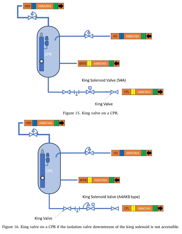
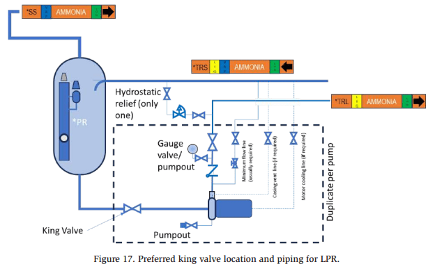
CPR
If a CPR is used and delivers liquid out to loads, the king valve should be on the CPL piping as shown in Figure 15. If the downstream isolation valve is inaccessible, the upstream isolation valve can be used if provision to protect the piping between the upstream isolation valve and the king solenoid is specified. In Figure 16 this is using a dual function regulator that is wide open when the solenoid is energized and has a factory set pilot upstream regulator that opens at the design pressure of the piping.
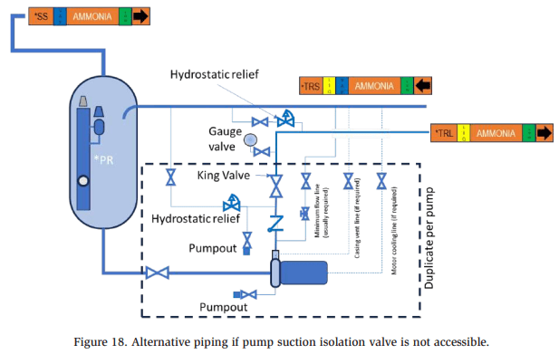
LPR
For a pumped recirculator, the king valve ideally would be the isolation valve on the pump suction; however, if that valve is inaccessible the piping details must be considered to ensure that hydraulic lockup of liquid is avoided. Figure 17 shows the preferred piping and king valve arrangement.
Note that the hydrostatic relief is downstream of the pump discharge isolation valve to protect the piping from hydraulic lockup and overpressure during a loss of power. The relief protects both the pumps and the recirculated liquid supply piping. For pump maintenance, the valve for the pump discharge gauge is used for pump out between the pump discharge check and isolation valve. For defrosting the pump, the suction valve can be closed, and the minimum flow line serves as a vapor pathway to the recirculated suction piping for the evaporated refrigerant. If a solenoid is used in the minimum flow line, it must be open to take full advantage of this piping arrangement’s benefit for defrosting the pump and king valve.
It is NOT recommended to put the minimum flow line between the discharge check valve and isolation valve or downstream of the two (2) pump discharge isolation valves because it will result in depressurizing the recirculated liquid line any time the pump is de-energized resulting in more difficulty in starting the pump. Further, if the pump is de-energized (e.g., local power failure or cavitation sensing) and the evaporator solenoids remain powered, the recirculated liquid piping will drain through the minimum flow line into the recirculator and require the pump to recharge the piping upon restart. If it is desired to de-pressurize the recirculated liquid line in the event of an emergency, a hydrostatic relief regulator with a wide-open feature could be used. No king solenoid is required, de-energizing the mechanical pump serves that purpose.
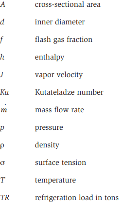
If the valve identified as the king in Figure 17 cannot be accessed, Figure 18 shows an alternative. This piping arrangement is not preferred due to the complexity of the relief protection to ensure protection of all possible locations for hydraulic lockup in the event that isolation of the king valve is necessary.
Operations
Operations will largely be the same as more traditional control methodologies.
Charging
Inbounding refrigerant will be to a vessel. The amount will be assessed at the variable level vessel (i.e., the last vessel on the float path).
Pump Down
Rather than storing the volume required for pump down of portions of the system for maintenance in the HPR, it will be stored in the variable level vessel. This volume will need to be accounted for on the sizing of that vessel no different than the sizing of an HPR in a more traditional design.
Conclusions
The use of float expansion valves for liquid makeup affords benefits from the use of solenoid/expansion valve control based on a controlled vessel liquid level. The main benefit is that the liquid makeup control is controlled by the refrigeration system flow rate and not the level sensed in the vessel. While the concept is easiest to implement in smaller, less complicated systems (e.g., single temperature level systems or distribution centers), larger systems can benefit as well. More complicated systems, like food manufacturing facilities, will also benefit, but may require some creativity with more than two temperature levels or smaller regulated evaporator loads.
The benefits of using float expansion valves are maximized by removing the need for high-pressure liquid (i.e., no HPR) and individually draining each condenser heat exchanger. This is also the biggest barrier to the application. Removing the need for high-pressure liquid delivery to loads is easily done and relatively common to see in current designs; however, removing the need for high-pressure liquid for oil cooling of rotary screw compressors will require using glycol for oil cooling. While this offers an opportunity for heat recovery, this is relatively rare to see in current system designs.
Current refrigeration system design would benefit from the use of float expansion valves to improve wintertime condenser operation, reduce the system volume by elimination of the HPR, and simplify and stabilize system controls.
Pipe Labeling
BD booster discharge
CD condenser drain
CPL controlled pressure liquid
ESS economizer (side-load) suction
FG foul gas (purger)
HPL high-pressure liquid
HSD high-stage discharge
HSS high-stage suction
LLSS low- low-stage suction
LLTRL low low temperature recirculated liquid
LLTRL low low temperature recirculated suction
LPL low pressure liquid LSS low-stage suction
LTRL low temperature recirculated liquid
LTRL low temperature recirculated suction
MPL medium pressure liquid
MSS medium temperature suction
MTRL medium temperature recirculated liquid
MTRL medium temperature recirculated suction
Vessel Labeling
CPR controlled pressure receiver
LLPR low low pressure receiver
LPR low pressure receiver
INT intercooler
MPR medium pressure receiver
Nomenclature
Subscripts
References
ASME, ASME Boiler & Pressure Vessel Code Sections VIII & XIII, 2021.
Faust, D., Simple Equations for Determining Mass Flow in Refrigeration Systems,
IIAR, 2022 Natural Refrigeration Conference & Expo Savannah, Georgia, Technical Paper #11, 2022.
IIAR, Ammonia Refrigeration Piping Handbook, IIAR, 2019.
Klysen, J.J., D.J. Ross, High Rise Warehouses: A growing trend for controlled-pressure receiver systems, 2007 Ammonia Refrigeration Conference & Trade Show, Nashville, Tennesee, Technical Paper #6, 2007.
Reindl, D.T., T.B. Jekel, Heat Recovery in Industrial Refrigeration, ASHRAE Journal, Vol. 29, August, 2007.
Yencho, J., Liquid Refrigerant Level Control – An Update, 11th Annual Meeting of the International Institute of Ammonia Refrigeration Annual Meeting, Austin, Texas, pp. 209-238, 1989.
Yencho, J., The Basics of Refrigeration Control Valves for Liquid Make-Up Applications, 2005 IIAR Ammonia Refrigeration Conference & Exhibition, Acapulco, Mexico, Technical Paper #9, 2005.
Yencho, J., Proper Application and Sizing of Metering Devices for Ammonia Refrigeration, 2013 Industrial Refrigeration Conference & Exhibition, Colorado Springs, Colorado, Technical Paper #8, 2013.
Acknowledgements
The author would like to gratefully acknowledge several behind-the-scenes contributors to ideas and concepts included in this paper. Bent Wiencke (Nestleretired) for his thought leadership on this topic and for is input in refining the various design details presented in this paper. Bent readily shared his experience in designing systems that have successfully utilized several of the float concepts presented. Tim Petrat (Witt), Harold Streicher (Hansen Technologies) and Adam Anderson (Danfoss) for unselfishly sharing their insights into the application of float valves in ammonia refrigeration systems and details related to successfully applying their specific products