2024 Technical Paper #3
Energy Savings in Ammonia Systems Using Low-Stage De-superheating
Author : Hannes Steyn (Pr.Eng.), Director of Heating and Refrigeration GEA Africa (Pty) Ltd
Abstract
This paper demonstrates how evaporative condensers can be used as low-stage de-superheaters to improve the efficiency of two-stage ammonia refrigeration systems. The high discharge temperatures generated by ammonia compressors can help reject heat to ambient heat sinks, thereby reducing the load on the high-stage compressors, which in turn reduces the required compressor motor power and provides energy savings for the user.
Introduction
In a global environment where energy demands and costs are constantly increasing, engineers are continuously motivated to design systems with improved energy efficiency. In the past, payback periods were the main driver for the implementation of efficiency improvements, but pressure on industries to reduce their carbon footprint (legislative and social) has accelerated these discussions.
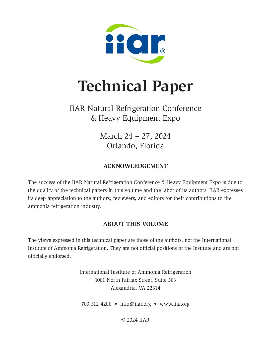
This paper demonstrates how low-stage de-superheating in two-stage ammonia systems can help reduce the peak power consumption of a plant, using established technologies. In a simple two-stage plant used for low-temperature applications, as illustrated in Figure 1, approximately 10%–13% of the induced load from the lowstage load is in the form of superheat. This is based on typical ammonia open-drive reciprocating compressor performance.
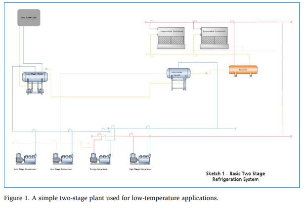
The pressure-enthalpy diagram below indicates the energy contained in superheated vapor between points 2 and 3 in the plant’s operating cycle. Although it is not possible to reject all this energy to ambient heat sinks because the operating temperatures are often above the saturation temperature of the intermediate condition, we considered several recovery options.
Concept Review
This study aims to evaluate the most practical alternative for reducing peak power consumption through low-stage de-superheating. The evaluation is conducted for a plant situated in a location with moderate to high ambient wet-bulb and drybulb temperatures. We exclude the evaluation of heat sinks, such as lakes and underground water reservoirs, because these heat sinks are not available to all plants. The evaluation is also limited to ambient air conditions (dry-bulb and wet-bulb temperatures).
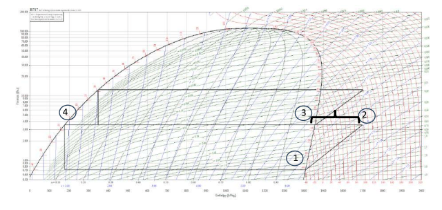
The first option includes a thermosiphon de-superheater inside the machinery room, installed in the low-stage compressor discharge line, as shown in Figure 2. The heat rejection is limited by the plant’s peak condensing temperature, 35°C (95°F) in this case.
The next option is to install an air-cooled radiator outside the machinery room, as shown in Figure 3. Initial selections of the air-cooled radiator indicate that the additional fan power offsets a significant percentage of the potential savings. It is also difficult to de-superheat the outlet gas temperatures to less than 10°C above the ambient dry-bulb temperature. This option was not considered further because of the high ambient dry-bulb temperature of 36°C (96.8°F).
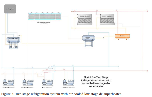
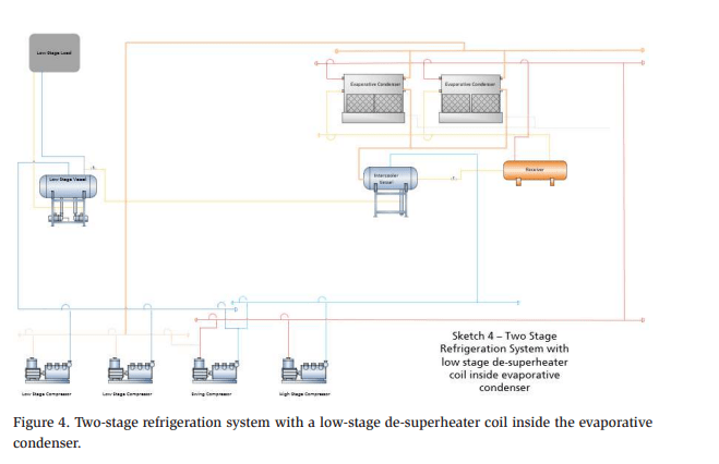
Both options may have benefits when overall power consumption is considered for plants operating in climates with low temperatures, but they are not considered further for this analysis. The option selected for evaluation is shown in Figure 4. Specifically, the evaporative condenser coil is split into two sections: a large section for normal condensing and a smaller section for de-superheating of the low-stage discharge vapor. This option is preferred because the ambient peak wet-bulb temperature is 22°C (71.6°F), and thus the de-superheating potential is increased compared with the alternative options. Furthermore, evaporative condensers can reject large amounts of energy while consuming low input power.
Preliminary Calculations, Assumptions, and Equipment Selections
Plant detail and environmental conditions
The plant has a low-stage load of 400 kW (113.8 TR) and requires a low-stage suction temperature of −40°C (−40°F) at the compressor. The plant also has a small highstage load, but this was not considered as part of this initial evaluation because we wanted to evaluate the reduction of the induced load. The saturated intermediate temperature is set to –5°C (23°F).
The ambient wet-bulb temperature is 22°C (71.6°F), and the ambient dry-bulb temperature is 36°C (96.8°F). The peak condensing temperature is 35°C (95°F).
The plant is situated in East London, South Africa (33.0198° S, 27.9039° E). All compressors and condensers are selected to operate using variable-speed drives.
Standard equipment selections
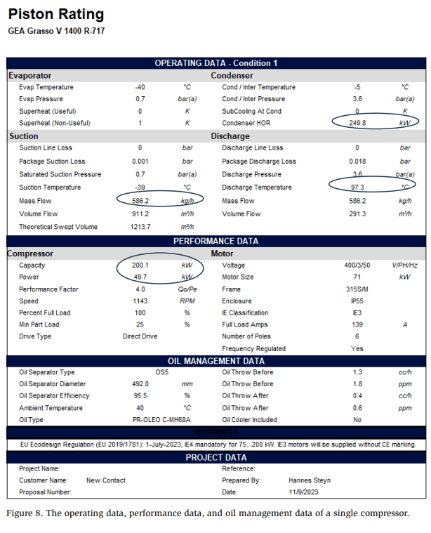
The original plant is configured as shown in Figure 1. Two booster compressors are selected, and the specifications are shown in Figure 5. The compressor speed is adjusted to show the exact expected operating point.
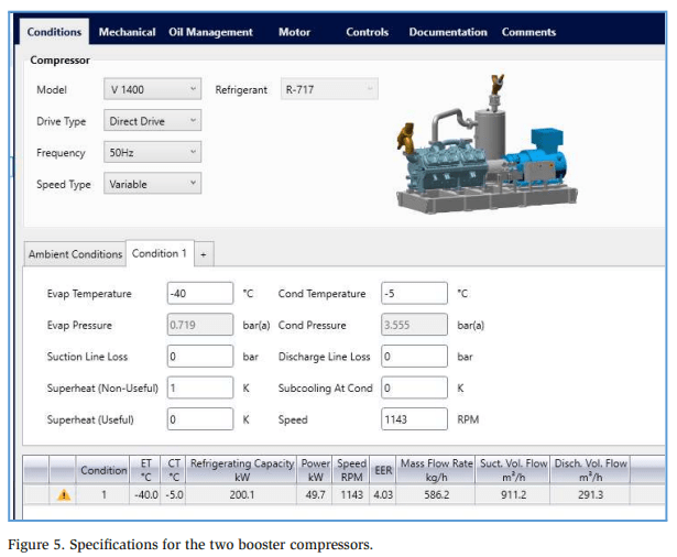
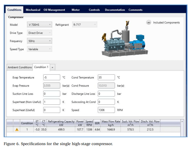
The two booster compressors have a combined induced load of 499.6 kW (142 TR). A single high-stage compressor was selected, and the specifications are shown in Figure 6. Again, we adjust the speed to indicate the exact expected operating point.
The total heat rejected by the high-stage compressor is 499.5 kW + 107.7 kW = 607.2 kW (172.6 TR). Based on this heat rejection and the design wet-bulb temperature, the condenser is selected with a 10% minimum safety margin. The specifications of the evaporative condenser are shown in Figure 7.
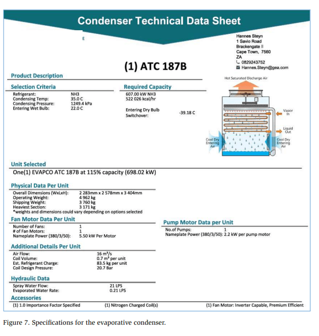
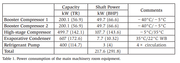
The power consumption of the main machinery room equipment is summarized below in Table 1.
Initial calculations of low-stage de-superheating
The compressor performance data for the low-stage compressor is outlined as follows (per compressor):
- Compressor capacity = 200.1 kW (56.9 TR)
- Compressor discharge temperature = 97.3°C (207.1°F)
- Mass flow through the compressor = 586.2 kg/hr (1292 lb/hr)
- High-stage induced load = 249.8 kW (71 TR)
- Compressor discharge pressure = 360 kPa (A) (52.2 psi)
Operating data, performance data, and oil management data are indicated in Figure 8.
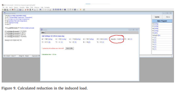
By assuming that we can reach 10 K (18°R) between the wet-bulb temperature and de-superheated gas temperature, the reduction in the induced load is calculated using EES software, approaching 10% (Figure 9). This is a positive result because highstage motor power is reduced by an equal amount. However, the system imposes additional pressure losses on the low-stage compressors and reduces the available condensing area.
Therefore, a trade-off exists. The more condenser circuits allocated to desuperheating, the lower the impact on the low-stage compressors and the greater the impact on the condenser. As an initial starting point, we limit the additional pressure drop to 25 kPa (3.6 psi) to minimize the impact on the power consumption of the low-stage compressor. Under these conditions, the low-stage compressor power increases by approximately 5% compared with the conventional system.
The selected condenser has 80 circuits with an overall circuit length of 18.26 m (60 ft). Using the EES Pipe-Flo tool, the number of required circuits can be estimated. The calculated result is shown in Figure 10, revealing that 10 circuits are needed for the low-stage de-superheating section to limit the pressure drop to approximately 25 kPa (3.6 psi). The result also indicates an internal heat transfer coefficient of 750 W/ m2 -K.
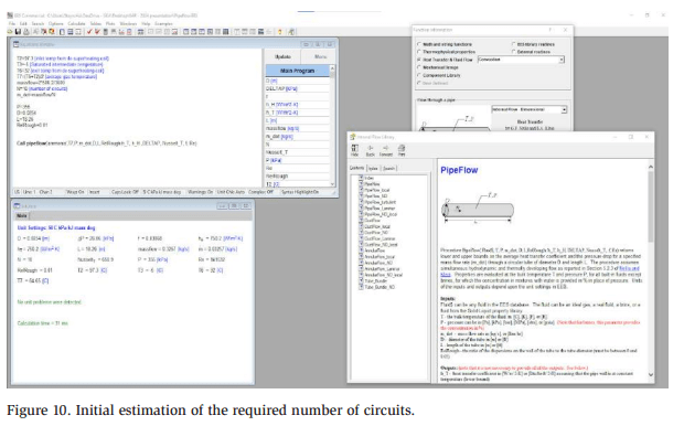
If 10 circuits (12.5%) are utilized for de-superheating, then 87.5% of the surface area is available for condensing. The real heat rejection capacity of the original condenser is 698 kW (198.5 TR), and if this is reduced by 12.5%, 610 kW (173.4 TR) of condensing capacity remain. Considering that the induced load is reduced by approximately 10%, the high-stage compressor requires a condensing capacity of only 545 kW (155 TR), leaving a 12% safety margin, which is within the design requirement.
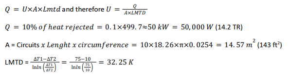
The last item to consider is the performance of the de-superheating coil inside the evaporative condenser. The heat transfer through the circuit is calculated as follows:

Substituting the above assumptions and calculations into the compressor selection software, we generate the results shown in Figure 11.
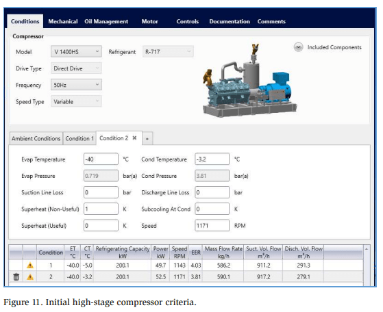
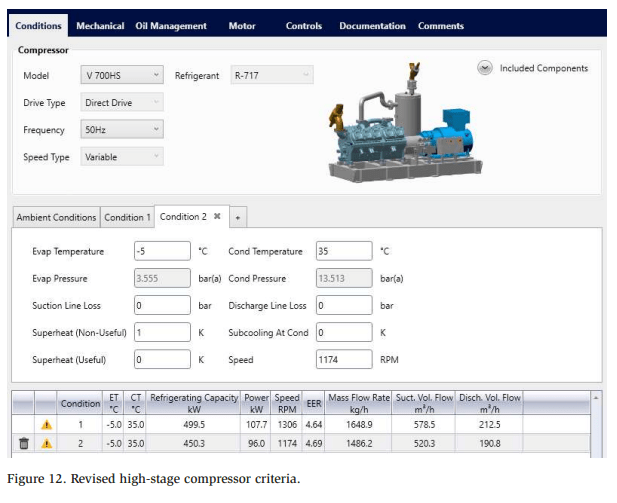
The induced load becomes 2 × (200.1 + 52.5) = 505.2 kW (142.6 TR). However, the higher discharge pressure also results in a higher compressor discharge temperature of 105°C (221°F), increasing the performance of the de-superheater to 55.2 kW (15.7 TR). The required high-stage compressor capacity is therefore 505.2 − 55.2 = 450 kW (128 TR), resulting in the updated high-stage compressor selection, shown in Figure 12.
The power consumption of the updated machinery room equipment is summarized in Table 2.
This modification results in a power saving of approximately 3%. For a low-stage freezer plant operating for 6000 hr/year at 80% average load, the reduction in electrical energy is calculated as follows: 6000 hr×80%×217.7 kW-211.7 kW=28,800 kWhr.. The annual reduction in electricity results in a cost savings of ZAR 72,000.00 (approximately USD 4000) based on an average local electricity rate of ZAR 2.50 per kWhr. Although the savings appear to be relatively small, they should be compared with the minimal additional costs. The cost can be calculated as follows:
- Cost for an additional circuit in the condenser ZAR 4,490.00
- Installed cost for 25 m of DN 100 (sch40) pipe ZAR 44,897.00
- Additional cost for two DN 100 stop valves ZAR 7,334.00
Total Cost ZAR 56,721.00
Contractor Mark-up (25%) ZAR 14,180.25
Total Additional investment ZAR 70,901.25 (USD 3,938.95)
Moreover, the system is simple and requires no additional maintenance. Therefore, the payback period is approximately one year.
Final Installation and Measurements
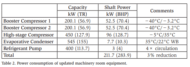
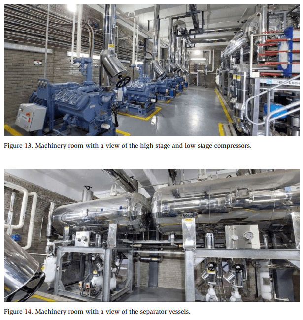
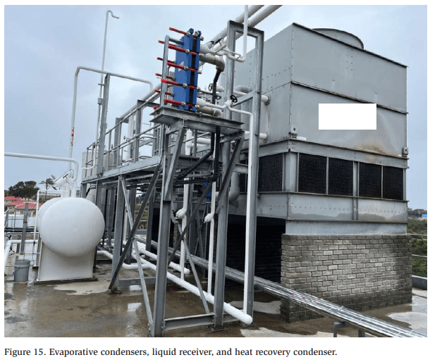
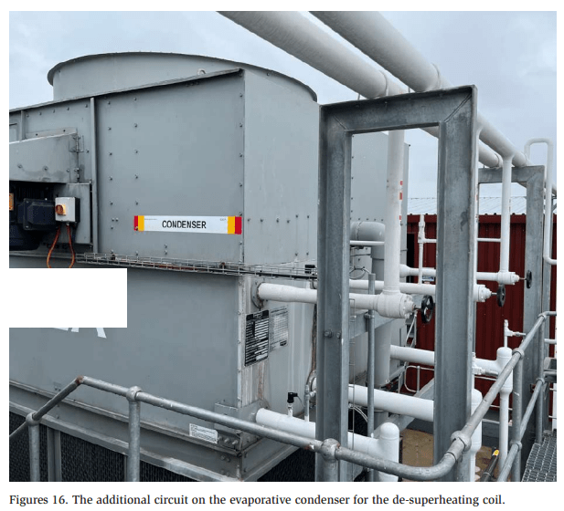
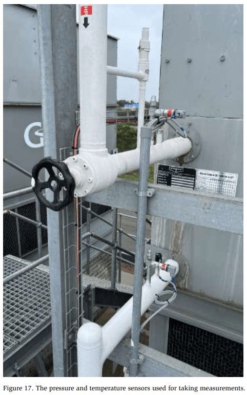
The on-site refrigeration system is a standard pump-circulation, two-stage ammonia refrigeration plant with reciprocating compressors, evaporative condensers, a liquid receiver, a −5°C (23°F) intercooler, and a –40°C (−40°F) low-stage vessel, as shown in Figures 13-17. The final installation is somewhat different from the original proposal because additional high-stage processes are added to the −5°C (23°F) vessel, and this changes the ultimate selection of the high-stage compressors and evaporative condensers. However, the low-stage compressors and low-stage desuperheating remain the same and can be tested on site.
Site conditions
During the testing and measurement process, we experienced a period of lower ambient conditions with dry-bulb temperatures ranging between 14 and 17°C (57 and 62.6°F) and wet-bulb temperatures between 13 and 15°C (55.4 and 59°F). Furthermore, the client did not run full production and only one low-stage compressor was in operation.
Testing methodology
To verify the data, the following steps are taken:
- Calibrate all temperature sensors and pressure transducers to ensure accurate data collection.
- Stabilize the low-stage load by adding hot gas through a throttling valve into the low-stage system. This allows the low-stage compressor to operate at a stable speed. The high-stage compressors are allowed to settle and match the induced load.
- The de-superheating coil on one condenser is closed to ensure that all the lowstage discharge vapor is channeled through a single condenser.
- Condenser fan speeds are manually set to 100% because the condensers are unloaded as a result of the lower ambient temperatures and lower load conditions.
- Once the plant stabilizes, data is recorded every 5 minutes for an hour.
Measured results
When the compressor has stabilized, the data points are all similar. Thus, we can focus on a single data series, as follows:
- Suction pressure = −37 kPa (g) (−5.366 PSIG)
- Suction temperature = −40°C (−40°F)
- Compressor speed = 1236 rpm
- Discharge pressure at cylinder head = 280 kPa (g) (40.6 PSIG)
- Discharge temperature = 113.9°C (237°F)
A software analysis of the measured suction pressure/discharge pressure and compressor speed generates the data shown in Figure 18.
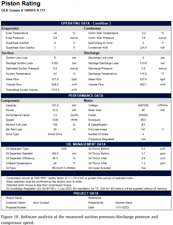
Notably, the calculated discharge temperature is very close to the measured discharge temperature under these conditions. As it is not possible to measure the mass flow on site, the manufacturer’s data sheet is used. The mass flow for the given conditions is 538 kg/hr (1186 lb/hr).
Additionally, the following data is measured:
- Ambient dry-bulb temperature = 14.3°C (57.7°F)
- Ambient wet-bulb temperature = 14°C (57.2°F)
- Inlet pressure to de-superheating coil = 264 kPa (g) (38.2 PSIG)
- Outlet pressure of de-superheating coil = 253 kPa (36.7 PSIG)
- Inlet temperature of de-superheating coil = 80°C (176°F)
- Outlet temperature of de-superheating coil = 18.7°C (65.7°F)
Comments on the observed data
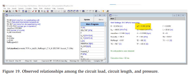
It is important to know that it was raining during the measurement. The low-stage discharge line was wet, and this may have enhanced the amount of de-superheating before the hot gas reached the de-superheating coil. In addition, the final condenser was slightly large, to cope with the additional high-stage load and two condensers, and thus 8 circuits were used for the de-superheating coil in each condenser.
This means that a circuit load of ![]() was tested (Figure 19). The circuit length for this condenser is 22.83 m. Re-entering these values into the EES Pipe-Flo function, we obtain a pressure drop of 9.98 kPa (1.45 psi), versus a measured value of 11 kPa (1.59 psi). Note that vapor outlet temperatures within 5 K of the ambient wet-bulb temperature were achieved for the entire test period. However, further performance testing is required closer to the stated design temperatures.
was tested (Figure 19). The circuit length for this condenser is 22.83 m. Re-entering these values into the EES Pipe-Flo function, we obtain a pressure drop of 9.98 kPa (1.45 psi), versus a measured value of 11 kPa (1.59 psi). Note that vapor outlet temperatures within 5 K of the ambient wet-bulb temperature were achieved for the entire test period. However, further performance testing is required closer to the stated design temperatures.
Conclusions
The results exceeded expectations considering that the approach temperature is closer to the wet-bulb temperature than originally anticipated, and more energy is therefore rejected to the atmosphere. The measured pressure drop is also consistent with the calculated values. Low-stage de-superheating can effectively be achieved with the use of split circuits in evaporative condensers. This reduces the induced load from the low-stage system by approximately 10%.
Furthermore, it is relatively easy and inexpensive to install. Condenser split circuits and uninsulated scheduled pipes are low-cost items in refrigerant plants, and the payback period should be short. A savings in capital expenditures is possible if smaller high-stage compressors are selected because of the reduced induced load, but the amount of savings varies from project to project. Moreover, different configurations of the de-superheating coil should be investigated further, and shorter circuits may improve the overall impact.
Overall, the evaluated system is ideal for traditional two-stage refrigeration plants and can even be retrofitted when condenser replacements are required, without the need for modifications to the other equipment or controls.
Resources
- GEA Heating and Refrigeration Technologies – RT Select Version 13.4.
- F-Chart Software – Engineering Equation Software Commercial Version 10.670.
- Evapco – Spectrum Version 2.2023.1031.1 C.