Technical Paper #11
CO2 systems: Lubricants and Oil Management Strategies
Author: Giacomo Pisano, M.Sc. Engineering, DORIN USA
Abstract
The use of carbon dioxide (CO2), especially in industrial refrigeration systems, has received a lot of attention in the last decades. As for any equipment, a correct lubricant choice and a proper oil management strategy are key for the safe, reliable, and efficient operation of refrigeration systems. This paper describes how to select the most appropriate lubricant, both from a compressor and a systems perspective. The lubrication properties, Daniel plots, viscosity drops, and system oil management of the most common lubricants used in CO2 refrigeration systems—polyolester (POE) and polyalkylene glycol (PAG)—are described. Oil management design features and guidelines are provided for the most common system configurations, including DX and pumped and overfed (ejector) executions, to select the optimal lubricant and oil management strategy for any application involving CO2 as the refrigerant.
Introduction
Selecting the most appropriate lubricant and its associated oil management strategy is key for a safe and reliable system operation
Transcritical carbon dioxide (CO2) applications are associated with large differential pressures, which induce specific loads in the compressor drive gear up to five times higher than those of HFCs, HFOs, and ammonia [1]. From a compressor perspective, the selected oil should provide effective lubrication to prevent premature compressor wear and failure.
Furthermore, lubricant dilution into the refrigerant is a key parameter to be considered when designing CO2 systems. The specific behavior of oil-to-refrigerant miscibility curves should also be considered, noting that CO2 solubility in the lubricant is higher than that of other refrigerants [1]. From a systems perspective, the selected oil management strategy should ensure that the oil carried over into the system is properly fed back to the compressor’s suction groups.
Lubricant selection from a compressor perspective
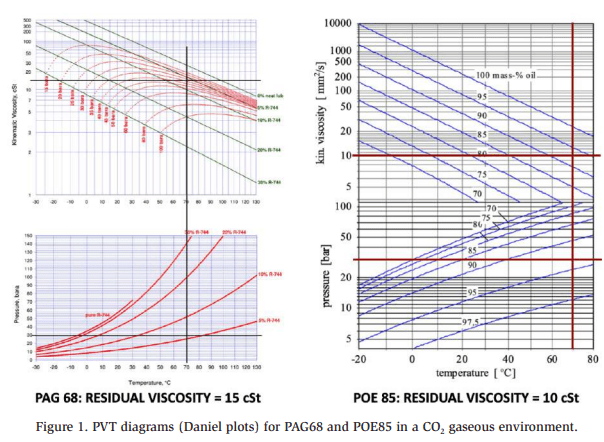
The most widely used lubricants in CO2 applications are polyolester (POE) and polyalkylene glycol (PAG) [2]. From a compressor perspective, both lubricants should be evaluated using Daniel plots that describe the pressure-viscosity-temperature (PVT) behavior of CO2 and the given lubricant. These plots allow for visually checking the amount of refrigerant dissolved into the lubricant and the viscosity drop experienced by the lubricant during its actual operation in the compressor sump.
The figure below shows the residual visual viscosity for both PAG68 and POE85 at an oil temperature of 60 °C (140°F) and 32°F SST. The plots reveal that the resulting mixture of oil and refrigerant indicates residual viscosities of 15 cSt and 10 cSt when using PAG68 and POE85, respectively. This outcome suggests that both lubricants can be considered valid options under these operating conditions but PAG68 performs better than POE85.
Munoz et al. [3] performed a detailed investigation using the same lubricants at unoz et al. [3] performed a detailed investigation using the same lubricants at different oil tempera.
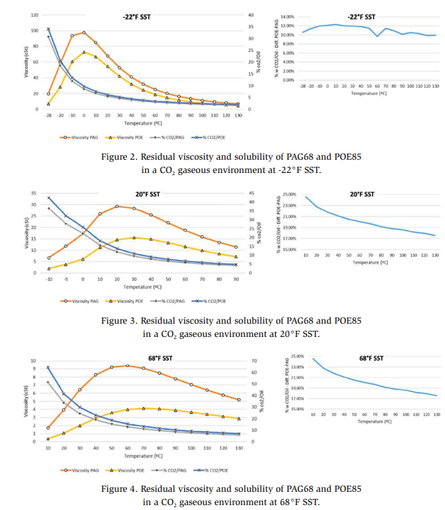
The previous figures show that PO85 absorbs more gaseous CO2 than PAG68 under all operating conditions. This result suggests that PAG68 is a more effective lubricant, as also indicated by the residual viscosity graphs, which show that PAG68 always exhibits higher residual viscosities. However, the real, practical compressor operating conditions should be considered because such conditions result in drive gears experiencing oil temperatures between 60°C and 80°C (140–176°F). Hence, in addition to PAG68, POE85 provides an acceptable residual viscosity at low and medium SST (e.g., -22°F SST and +20°F SST). Nevertheless, if higher SST values are considered (e.g., in the case of heat pumps, with 68°F SST), POE85 is no longer an option because it results in low residual viscosity.
Notwithstanding, the PVT diagrams for PAG68 and POE85 show that both types of lubricants can be used in a wide range of applications (low temperature (LT) with SST of -22°F and medium temperature (MT) with SST of 20°F). However, this theoretical behavior should be verified through internal tests, which typically include:
- Steel ball test: This test determines the load-carrying capabilities of a lubricating grease under high-load applications.
- Compressor qualification test: This test is used to formally approve a compressor design before its commercial launch.
The figures below illustrate the results of the laboratory steel ball wear tests, using POE85 and PAG68. The figures show the wear width and sliding surface appearance obtained in the tests at pressures of 70 bar (1015 psi) and 80 bar (1160 psi).
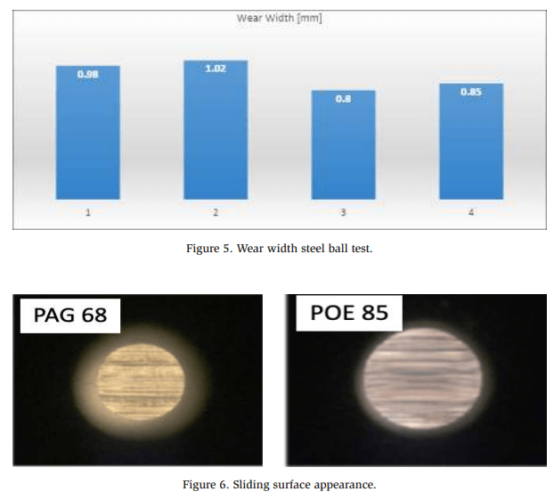
Steel ball wear tests demonstrated that PAG68 performed slightly better than POE85 in terms of wear width and surface appearance. The wear width measured using PAG68 peaked at 0.85 mm with an 80-bar load, against the 1.02 mm wear width measured with POE85. Furthermore, the surface appearance was smoother, with fewer scars per mm2 , when using PAG68. Nevertheless, even if POE85 performed slightly worse than PAG68, the measured data indicate that both lubricants are suitable for CO2 compressors.
However, the steel ball wear test alone is insufficient to assure reliable compressor operation throughout its lifetime. Thus, specific qualification tests are generally conducted by compressor manufacturers before commercial launch [1]. These tests were also performed in our case, with satisfactory results for both PAG68 and POE85 in low- (e.g., -22°F SST) and medium-temperature (e.g., +22°F SST) applications.
The figures below display the components of the same compressor models after being subjected to qualification tests using PAG68 and POE85.
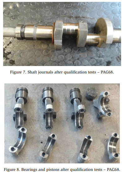
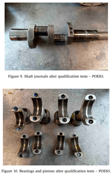
The figures prove that both PAG68 and POE85 can be used with CO2 in low- and medium-temperature applications. In particular, PAG provided a slightly lower surface polishing on the shaft journals and a slightly lower wear rate on the bearing surfaces.
Lubricant selection and oil management from a systems perspective
Lubricant choice and oil management strategy are among the most important factors to be evaluated when designing a CO2 refrigeration system. The choice between PAG68 and POE85 should be made keeping in mind several parameters, one of the most important being considerably different miscibility with liquid CO2.
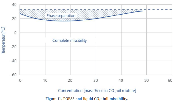
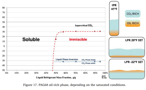
While POE85 is fully miscible with liquid CO2 in the most common evaporating temperature ranges [4], PAG68 is only partly miscible [5], as shown in the figures below.
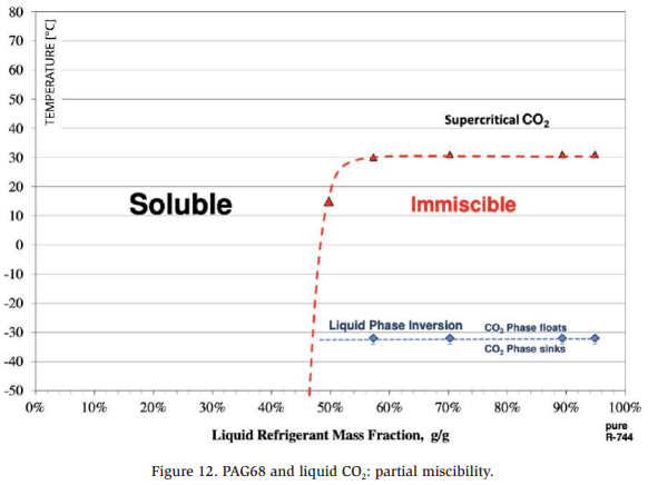
The previous figure shows how PAG68 becomes less dense than liquid CO2 below –32°C (–25.6°F) SST; in other words, it sinks above this temperature and floats on top of liquid CO2 below this temperature.
The features of the aforementioned oils make the difference in terms of lubricant choice. No lubricant can fulfill all the needed lubricity and miscibility requirements; thus, lubricant selection and oil management are case-specific. The following chapters provide guidelines for the design of the most common refrigeration systems (dry expansion and pumped and overfed (ejector) executions of a CO2 booster transcritical installation).
Oil management – Dry expansion CO2 booster system
The most typical dry expansion (DX) CO2 system architecture is represented by a booster flash gas bypass execution, which can be improved from an efficiency standpoint by adding parallel compression [6]. The figure below shows a simplified sketch of a booster parallel compression system, including the oil management strategy.
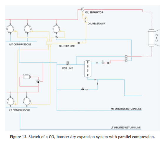
Three compressor suction groups can be identified in this figure: the low temperature (LT), medium temperature (MT), and parallel compression suction groups. The LT suction group compresses the gas stream coming from LT utilities. When parallel compressors are not engaged, three contributions make up the MT suction stream: LT compressor discharge, MT utilities return line, and flash gas bypass line. The MT compressors discharge the stream; therefore, this group contains the total system’s CO2 mass flow but also contains the oil entrained from both MT and LT compressors. If parallel compressors are engaged, their execution follows the MT suction group.
Therefore, an oil separator is placed after the MT and parallel compressors’ discharge to separate the lubricant from the refrigerant. This arrangement allows almost pure CO2 to move toward the gas cooler. The oil being separated accumulates in the separator’s bottom and is then fed toward the LT, MT, and parallel compression suction groups. The lubricant is normally fed back to compressors, using oil floats and controllers. When the oil level is below a certain threshold in a given compressor sump, a solenoid valve opens its specific return line, allowing the oil level to be replenished in the compressor.
However, oil separator efficiency is not 100%. Various oil separators are available in the market, with manufacturers declaring separation efficiency up to 98% [7]. Thus, although a substantial part of the oil entrained by the LT, MT, and parallel compressors is effectively separated, a small mass fraction of the lubricant keeps moving toward the gas cooler and through the utilities. This small amount of lubricant should be recovered in a timely manner to avoid a lack of lubrication in the compressors. POE85 and PAG68 perform well in typical booster DX systems; both lubricants exhibit adequate oil return properties once the refrigerant is fully evaporated. There are more than 35,000 CO2 DX systems running worldwide, either with POE85 or PAG68, evidencing these lubricants’ effectiveness [8].
In addition, pipe runs should be properly executed to ensure that oil returns from the gas and utilities to the rack. The following figure provides some indications in this sense.
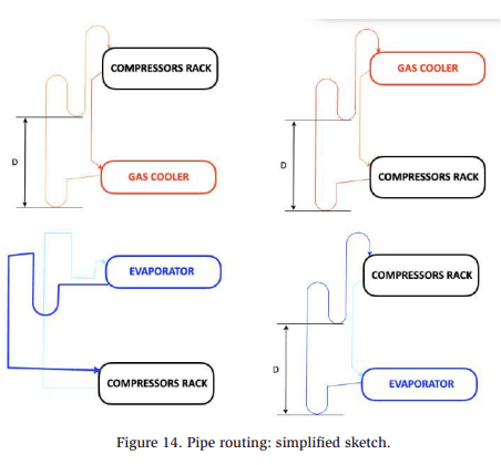
This figure’s main takeaways relate to the distance between raisers, which should be around 6 ft., and the slope of the horizontal pipes, which should trend downward, following the direction of the flow, descending 1″ for every 20 ft.
CO2 systems are often questioned regarding their energy efficiency because of their power consumption in warmer climates, where coefficient of performance (COP) values are normally penalized when no technical solutions aiming at lower power consumption are introduced. Flooded and overfed configurations, such as pumped systems and ejector technology, help improve performance [6]. However, these implementations bring new challenges from a lubricant choice and oil management perspective. These challenges are described in the next sections.
Oil management – Pumped CO2 booster systems
Pumped CO2 execution is quite popular in industrial refrigeration systems or winter sports venues, such as ice-skating rinks. In such systems, liquid CO2 circulates into the evaporators and accumulates in a low-pressure drum. When the drum pressure increases, compressors are engaged to maintain the drum pressure at the desired level. The figure below presents a simplified sketch of a low-temperature, transcritical CO2 pumped system.
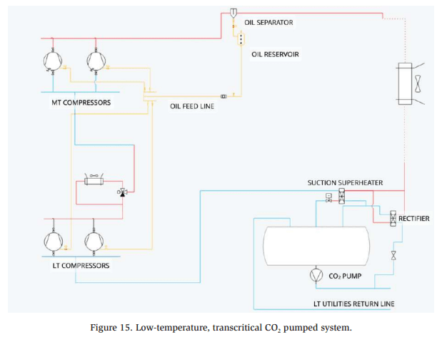
Oil separators do not attain 100% efficiency; thus, a certain amount of oil ends up flowing into the low-pressure drum, together with liquid CO2. This oil is normally recovered using a rectifier, which evaporates an oil-rich CO2 flow bringing the lubricant toward the compressor suction line.
However, as mentioned in Section 4, care should be taken regarding lubricant selection: POE85 is fully miscible with liquid CO2, whereas PAG68 is partly miscible with liquid CO2 and features density inversion below -32 °C (-25.6°F) SST.
Hence, when a CO2 pumped system for typical MT operation (-10°C/14°F SST) is considered, both POE85 and PAG68 can be recovered via a rectifier. However, when it comes to an LT system, typically operating at -40 °C (-40°F) SST, POE85 becomes the preferred solution. At such a low saturation temperature, PAG68 floats on top of the CO2, complicating its recovery using a standard rectifier.
Therefore, both POE85 and PAG68 are valid options for typical MT pumped systems, whereas POE85 is the preferred solution for LT operations.
Overfed CO2 booster systems
The performance penalties of using CO2 have been questioned in the case of high ambient temperature operations. This is especially concerning regarding the overall COP of the system. Therefore, this issue has been tackled with the implementation of numerous technical solutions, such as ejectors, since 2013 [6]. A typical CO2 booster system layout, including ejectors, is shown in the figure below.

Ejectors help improve the system’s efficiency. In particular, liquid ejectors allow to run utilities overfed, with no superheat, thus optimizing heat transfer and minimizing the evaporator’s ∆T [6]. However, this means that a portion of the liquid refrigerant is likely to come back to compressor suction with time, necessitating the use of a generously sized suction accumulator to avoid compressor damage and premature failure.
From an oil management perspective, an ejector-based overfed system is associated with several considerations. As mentioned, oil separators do not achieve 100% efficiency; thus, some of the oil will find its way toward the gas cooler, the intermediate pressure receiver, and the utilities and suction accumulator. Therefore, a reliable oil management strategy should be in place to periodically recover this lubricant. The parts of the system where this oil recovery could be most easily attempted are within the system receivers (e.g., the intermediate pressure receiver (IPR) and/or the suction accumulator).
However, because POE85 is completely miscible with liquid CO2, removing it from the refrigerant is challenging unless rectifiers are used. Nevertheless, doing so would partly void the zero-superheat efficiency gain introduced with the ejector technology.
Therefore, PAG68 is a simpler, more efficient, and safer lubricant solution for CO2 refrigeration systems including ejector-based overfed systems. When considering the saturated conditions in the suction accumulator (-6°C/22 °F) and the intermediate pressure receiver (5°C/41°F), it is evident that PAG68 will always be denser than liquid CO2, thus sinking in the vessel’s bottom and making it easier to recover.
The figure below summarizes how PAG68 stratifies and creates oil-rich zones in a vessel where liquid CO2 accumulates, depending on the vessel’s saturated conditions.
Conclusions
This work dealt with lubricants used in CO2 refrigeration systems, both from a compressor and a systems perspective. The two most common lubricants used in such systems are POE85 and PAG68.
Compressor-wise, both lubricants were appropriate as they exhibited an acceptable viscosity drop and thus assured a proper oil film with the correct viscosity throughout the compressor’s lifetime.
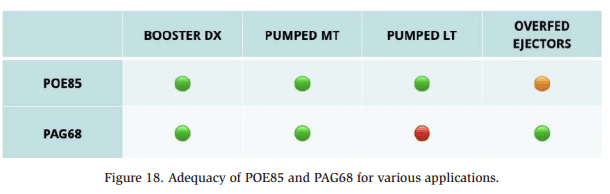
On the other hand, there are specific considerations regarding the oil management strategy, depending on the system’s design. Several configurations were considered and the findings are summarized in the figure below.
References
[1] Pisano, G. “Transcritical CO2 compressors: Technical challenges in industrial refrigeration applications.” – IIAR 2022 Conference. [2] Karnaz, J. “Compressor designs, lubricant options and refrigerant selections: Putting the puzzle together.” – Shrieve Technical Literature. [3] Munoz M., Dixon L., Seeton C.J., Karnaz J. “The role of lubricant chemistry in a R744 refrigeration plant.” – IIAR 2017 Conference. [4] RENISO “Refrigeration oils.” – Technical Literature 2020/21. [5] SHRIEVE “Zerol RFL 68-EP with R744.” – Information Bulletin 2014. [6] Pisano, G. “CO2 systems add-ons: Calculations and field measurements” – IIAR 2024 Conference. [7] TEMPRITE “Oil separators – 130 series.” – Technical Literature 2024. [8] SHECCO “Market trends” – Atmo US 2024.