Don’t Curse the Purger
DON TRAGETHON CIRO, CRST, RAI | REGULATORY LIAISON, WESTERN PRECOOLING
ABSTRACT
The goal of operators, contractors, and design engineers is to operate a closed loop refrigeration system as close to design intent as possible. The owner wants maximum value from the equipment and personnel employed at the facility. The presence of gases that do not liquify within the operating conditions add cost to the running of the system.
INTRODUCTION
“Purging” is the process of removing unwanted gases from a refrigeration system. Purging can be performed manually or can be accomplished using specialized equipment that concentrates the non-condensable gases and eliminates them from the system as needed.
The company purchased and properly installed two identical multi-point autopurgers at two separate facilities in the same community. The facilities provide batch precooling services and short term storage of cooled products in 32°F cold rooms. Both purgers functioned well at first, but soon both units suffered random liquid ammonia discharge through the bubbler, which resulted in facility evacuation and system shut-down. All components checked out “good,” and it was presumed that purge discharge solenoid valves were hanging open when they should not. The vendor was called in to check the installation and provide technical support. Everything was in good order. The suspect solenoid valves were replaced but the random releases continued, albeit sporadically. The company cursed the purger and abandoned it in place, vowing to never buy that brand again.
AUTOPURGERS ARE NOT “NEW” TO THE COMPANY
Discovering the source of the problem
The company has been using autopurgers from this manufacturer since the mid1980s. The purgers would be moved from location to location to remove noncondensable gases (“air” for the remainder of the paper) from high-side equipment installed on a seasonal basis in the Southwest United States. Prior to the purchase of the first autopurgers, purging was conducted manually. 1
As this paper explains, the problem can happen to any brand of purger.
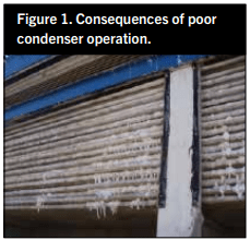
Head pressure was a challenge due to scale accumulating on equipment insulating the heat transfer surface. Not only was heat transfer impaired by a thick scale jacket, the velocity of the air passing the coil tubes increased. Faster air speed meant less residency time of air/ water interfacing the coil surface, which was confirmed through observation that two-thirds of the coil tube was “dry” in appearance. The dry area developed a “beard” of scale stubble from the 4 o’clock position down and around to the 8 o’clock position of each horizontal pass of the coil. With fans operating at full speed, two-thirds of each tube pass operated “dry” because of the speed of the fan air transiting from below. Consequently, one-third of the heat transfer surface did not receive adequate contact with the air/ water that should have enveloped the entire tube. The water treatment effort was not sufficient: regulations forced a change of treatment material to polymers and the water conservation effort thwarted blow down. It was an ugly period of trial and error. All these issues resulted in higher condensing pressure.
The problem compounded as weeks went by. The scale beard became thicker and the distance between tubes decreased. The speed of the air passing through the coil bundle increased, while the tubes ran “dryer” and the head pressure ran higher.
There were times when it appeared there was 25 psi or more of excess pressure due to non-condensable gases. Manual purging was the only approach at that time.
Where we learned to purge manually
In those days the Refrigerating Engineers and Technicians Association (RETA) published Industrial Refrigeration Course 1 (IR-1), with the last chapter instructing about purging. Measuring drain leg liquid temperature and pressure from the condenser outlet and comparing the two values with the saturation table for the refrigerant indicates if the fluid is solely refrigerant or a mix of refrigerant and air.The publication explained how to purge while operating. The guidance was to purge where the gas and liquid flow would be the least. This is at the condenser outlet and from the top of the high pressure receiver where gas should be slowest and coolest.
In the mid-1980s, operators assigned to purging duty were drilled on RETA’s IR-1, which states that discharge from a manual purge process can lose 100 times more ammonia than a refrigerated purger. Operators would often comment that the odor coming from the water in the pails and barrels that were “blown down” into was quite ripe indeed. It was during those purging assignments that I observed strange behavior. There were times that the discharge from the ¼” purge hose (the typical red air hose available from the NAPA store back then) would deliver a robust stream of air bubbles to the bucket. At times, the flow through the hose would change and it began to kick and squirm. Frost formed on the hose. The sound of the flow into the bucket would change to a raspy growl and the hose was at risk of being ejected from the top of the bucket by the recoil at the discharge.
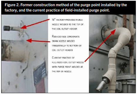
As a result, flow through the purge valve had to be throttled back until the violent behavior subsided. Before long, the frost would melt away and air bubbles were seen in the buckewe wereAfter several of these experiences, I came to realize that the liquid ejection would happen when the refrigeration load decreased. It appeared to me that the liquid was gathering in the condenser coil and “bottling up” in the circuits. In those days it was common practice for a condenser manufacturer to design coil circuits with 4” inlet connections and a 2” outlet connection (Figure 2). The outlet connection was installed flush with the bottom of the drain header to assure full drainage as liquid reached the end of the coil circuits. There was a bent 1/2” schedule 80 nipple to purge from. The nipple was welded to the top of the condenser drain header to direct refrigerant and non-condensables (foul gases) to the purge line for expulsion. This was the case for the condensers I purged in the 1980s. The build-up of scale on the coils caused extended reaction times to changes in conditions; very sluggish responses to load changes masked the causes of the discharge pressure issues.
We were taught that the condition of the refrigerant is always saturated at the discharge of the condenser. I do not agree with that “absolute statement,” and find at times that the refrigerant can appear to be subcooled as it drains out.
The mystery surrounding the condition of refrigerant leaving the condenser
The RETA student guides and equipment operating manuals are written from the viewpoint that the system is operating at a “steady state.” Systems used for process cooling (blast freezing, precooling, water chilling, anything that is a “batch process”) do not enjoy steady state conditions. When the load is minimal, the discharge pressure will come down because there is not as much refrigerant being shoved into the condenser minute-by-minute as there is when the process load kicks in. A plant may be operating at 25% capacity and then the load quickly increases to 100%. The flow rate of refrigerant may quadruple into the condenser(s) in minutes. The system condensing pressure increases as does the temperature of the condensate, but the system responds to sudden changes at different rates: the pressure rises sooner than the corresponding condensate temperature. The RETA IR-1 now states that the system needs to be running in a steady-state configuration for at least half an hour before taking pressure/temperature readings to evaluate for air. I have observed a system appear to suffer 25 psi excess pressure and the same system appear to have 3 psi excess pressure due to non-condensables. The only difference was when I took the measurements and how “hard” the system was working at the time of measuring.
So, which do you believe? That is the beauty of having an autopurger on the system because it can sort things out. The autopurger condenses a sample of foul gas and concentrates the gas at discharge pressure in a chamber, ready to discharge into an active ammoniaabsorbing “bubbler” and sends the effluent down the sanitary sewer system where it will do no harm. The discharge from the purger is to be a benign flow into the wastewater system. However, other things happen now and again that are highly problematic.
CAUGHT “RED HANDED”
Look for the exception in the process instead of the usual conditions
It had been many months since the owners gave up on their investment in two autopurgers at the facilities. The time finally came when proper attention could be given to the problem. After reviewing the paraphernalia available from the autopurger manufacturer, it was concluded that everything was correctly installed and the automation working properly. Yet, liquid would occasionally discharge through the bubbler causing it to violently jerk and twitch. The flow of liquid into the diluting water stream causes an intense response that is absorbed physically by the purger’s bubbler system, and the sanitary sewer system has to handle the effluent coming down the line to it.
The facility where the cause of the trouble was discovered has two equally sized condensers which receive proper water treatment and care. There is no scale on the surfaces. The two condensers discharge into their own horizontal collection header, downstream of the P-traps of each coil (Figure 3).
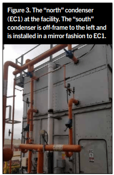
Each of the four condenser coils has a solenoid-controlled purge point. Again, the installation was built as designed by a competent and reputable contractor. The discharge from each 6” horizontal collecting drain header dropped through the ceiling into the engine room. The flow from the two condensers comes together and enters the side of a thermosiphon pilot receiver for the oil cooling system of the four compressors. The condenser fans and pumps work in tandem. Pumps come on together first, then fans start as required for floating head pressure. The condensers essentially split the load equally. The typical head pressure is 135 psig at light load and 150 psig at full load.
While checking for non-condensable gases, something was found to be amiss at the 4” condensate drain lines (Figure 4).
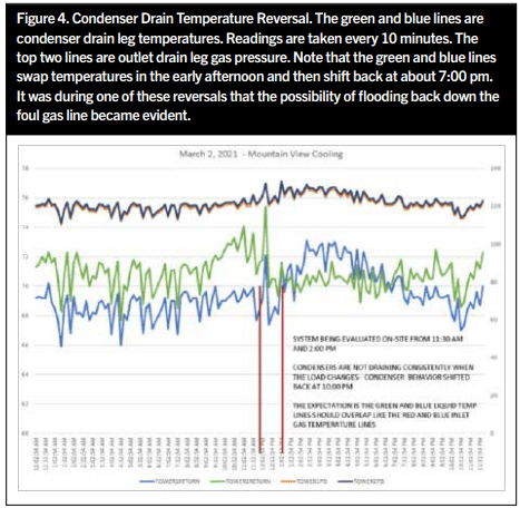
The temperature of the liquid in the “north” condenser collector header approximated the wet bulb temperature that day. The companion (south) condenser’s drain temperature was as expected and in agreement with saturation. So, one condenser was discharging subcooled liquid while the other was delivering saturated liquid to the thermosiphon pilot-receiver. If everything is being controlled in the same manner, the same outcome should be expected from the condensers. However, when the fourth compressor (500 hp ~ 30% of the capacity of the system) came online and loaded up, the condenser that previously was running “properly” began to discharge subcooled liquid. At the same time, the companion condenser that was running improperly began to properly discharge saturated liquid.
This was happening at random, leading to a quite perplexing situation. Then came the Ah-ha! moment. Review of the purger’s plumbing schematic (Figure 5) shows that the foul gas comes down from the purge point above.
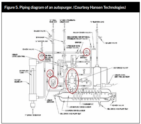
There are many references in the operator’s manual and troubleshooting guidance from the manufacturer that state that liquid might be coming from a purge point or other location causing problems. The factory warned of this possibility, but the plant was installed and controlled as designed. It isn’t reasonable to suspect something going amiss with control or design. The purger is designed with a mechanical float valve that is to take “casual” condensate that forms in the foul gas line and direct that liquid through a metering device into the evaporator portion of the foul gas concentrating evaporator. This is a small, yet very reliable, float valve. It is designed to handle liquid that forms slowly and deliver that liquid to the evaporator side of the purger concentrating evaporator. Excess flow through the valve returns to the compressor suction from the evaporator chamber, most likely through some sort of suction accumulator that provides protection for the compressor. No harm will come from that.
Upon closer examination of the plumbing diagram, it can be seen that the liquid gathering in the “dome” of the foul gas concentrator section (the section with the ball float in it) raises the ball, operating a magnet to an attractor, and closing a switch that sends an input to the controller of the purger. The signal instructs the purger to cease discharging air and return to concentrating foul gas into liquid. Under normal conditions, this float switch assembly works just fine as the change of apparent liquid level in the concentrator chamber happens very slowly. However, what if the purger control indicates it is time to discharge air to the bubbler (the float ball has dropped to the “call” position), and the purge point being drawn from suddenly becomes flooded? This would lead to a ¾” schedule 80 pipe that may be fifty to sixty feet in length starting thirty feet above the purger flowing liquid ammonia through it to the tiny float valve that is supposed to handle occasional “casual” liquid formation. Fifty feet of ¾” pipe will have 1.14 gallons of tepid high pressure liquid in it.There will be upwards of a 115 psi pressure differential between the purge point and the 1 psi metering orifice that is to control the flow of discharge into the bubbler. When the autopurger shifts into “purge” mode, a solenoid valve opens that conducts non- condensable vapor from the concentrator to the bubbler, and sends fresh water to the bubbler. The signal to purge is sustained until the ball of the float switch rises up with the liquid level in the concentrator section.
The flow of liquid being pushed by condenser pressure down this pipe is rapid and extreme. The volume itself will completely fill the concentrator section of the purger with liquid, and very suddenly. The float ball has dropped to indicate purging is required, but the liquid rushing into the float ball chamber will come in so fast that liquid will surround the ball completely, locking it into place. The buoyancy of the ball is not enough to overcome the liquid lock-up above the ball, and the switch cannot transfer from the “call” to the “satisfied” signal. The purger will release liquid ammonia from the purger continuously until there is enough liquid to allow the ball to float up and transfer the signal from “purge required” to “no purge required.”
The shaking then ends, but truck drivers and site employees may have already been chased out of the restrooms by ammonia vapor backflowing from the facility’s sanitary sewer system.
CONCLUSION
Don’t curse the purger; it is not at fault. The occasional combination of conditions to bring about random liquid flow into the purger’s bubbler is an example of the “Swiss cheese” method of a risk and hazard analysis. The unhappy event will not occur unless the holes of the Swiss cheese align themselves to allow passage of conditions to set off the undesired situation. The holes in our cheese are:
- System load changes affect the condensers in a way that causes liquid to gather deep enough in a condenser discharge pipe to draft liquid down from a purge point.
- The purge point that is backfilled is active at the time of purging.
- The purger activates the purge function, causing a significant pressure differential to draw refrigerant down from the purge point (which may be liquid laden).
- There is no “intelligence” to stop the purging when this random event occurs.
- Even minor differences in pressure will cause liquid to hang up and cause a flood- back from paired condensers.
WHAT TO DO ABOUT IT?
Consider the options:
- Bring the foul gas line from the purge points off the condensers to a small high pressure vessel to serve as a trap to accept the flow of liquid.
- Amend the controls to force the continued purge sampling signal from the AP-08 to draw from the top of the high pressure receiver. We have confidence that the receiver will not send liquid to the purger through the foul gas line.
Consider what will work:
- Consideration #1 will be difficult to figure out – just how large will this additional vessel have to be to reliably intercept liquid flow from a back-filled purge point? This would be a challenging puzzle to solve. The vessel would need to be large enough to intercept the flowing liquid and it would need to provide a separation capability when the potential pressure drop is 100-plus psi through the vessel.
- Consideration #2 will be the “easiest” approach to a solution. There is no piping or vessel changes involved, and no additional pressure relief valves added to the mechanical integrity program. There will be no vessel maintenance with cold/ warm skin temperatures that bring on paint degradation and corrosion, and no liquid transfer operation to add to the system to rid the unwanted overflow.
Option #2 looks appealing at this time. Most likely a programmable logic controller (PLC) will be installed and programmed to take the commands from the purger output board and change the timing of purge-cycle steps to ensure a smooth transition from “concentrate” to “purge” actions.
Our group will be conducting a Management of Change (MOC) with a risk/reward analysis to decide an approach to solving the problem now that we understand why it sporadically occurs. The first step is to investigate whether or not the foul gas passing solenoid valve #4 in Figure 5 remains open while purge solenoid valves #5 and #6 are energized. My recollection is that the purger is allowed to sample full- time whether releasing noncondensables or not. A simple singlepole, double-throw relay triggered by the signal to solenoid valve #5 may provide the least expensive after-market solution. If we find that it is necessary to continue to supply condenser pressure to the purger’s evaporator during a purge cycle, we will investigate applying a PLC to transfer the gas supply to the purge point on top of the highpressure receiver. A different solution may emerge as the group of facility professionals get together to problemsolve. Simply leaving an untrustworthy $30,000 apparatus offline is not an acceptable solution and illustrates poor stewardship of the refrigeration system.
ACKNOWLEDGEMENTS
Hansen Technologies Corporation AP003h – 2015 operation and maintenance manual
Hansen Technologies Corporation Techni-Brief March 2005 Volume 4 guide
RETA IR-1 course book – Chapter 10
Western Precooling Systems