


2025 Technical Paper #9
Lessons Learned from a Collection of Ammonia Incident Investigations
Author: C’Anna Wiens P.E., Process Safety Engineer, Resource Compliance
Abstract
You may be familiar with the quote, “Those who do not learn from history are doomed to repeat it.” Learning from others’ mistakes can be a game-changer in the world of ammonia refrigeration. This paper contains a collection of accounts of ammonia releases and interesting details from each incident investigation. Read about roof collapses, flying fan blades, and ruptured nurse tanks as you dive into the stories of what went wrong, and how to avoid repeating these events in the future. Each story in this paper includes a detailed description of the incident and the contributing factors leading up to the release. Many of the release calculations are provided along with the basis for the assumptions made.
Introduction
When working with a hazardous material like ammonia, an accidental release can easily take lives or cause injuries. No matter the size of an ammonia system, one should never downplay the gravity of an accidental release. Learning about mistakes made and lessons learned can be valuable when confronting a comparable situation in your own backyard. One of the goals of this paper is to educate about the possibilities of what could go wrong, and how following today’s codes and standards can reduce the likelihood of disaster.
The second focus of this paper is the process of performing a release calculation during an incident investigation. Ideal circumstances are rarely encountered when performing these calculations, so assumptions must be made. For example, when measuring the area of a hole where a leak occurred, the shape of the hole will most likely not be a perfect circle. When a hole develops from corrosion, the hole will have jagged and uneven edges, making it difficult to determine the exact area of the hole. The release calculations in this paper include various strategies and creative solutions that were used to obtain as much accuracy as possible.
Whether you hope to be better prepared against potential hazards or learn more about how release calculations are performed, the incident investigations described in this paper can lend insight to anyone.
Roof Collapse
Summary
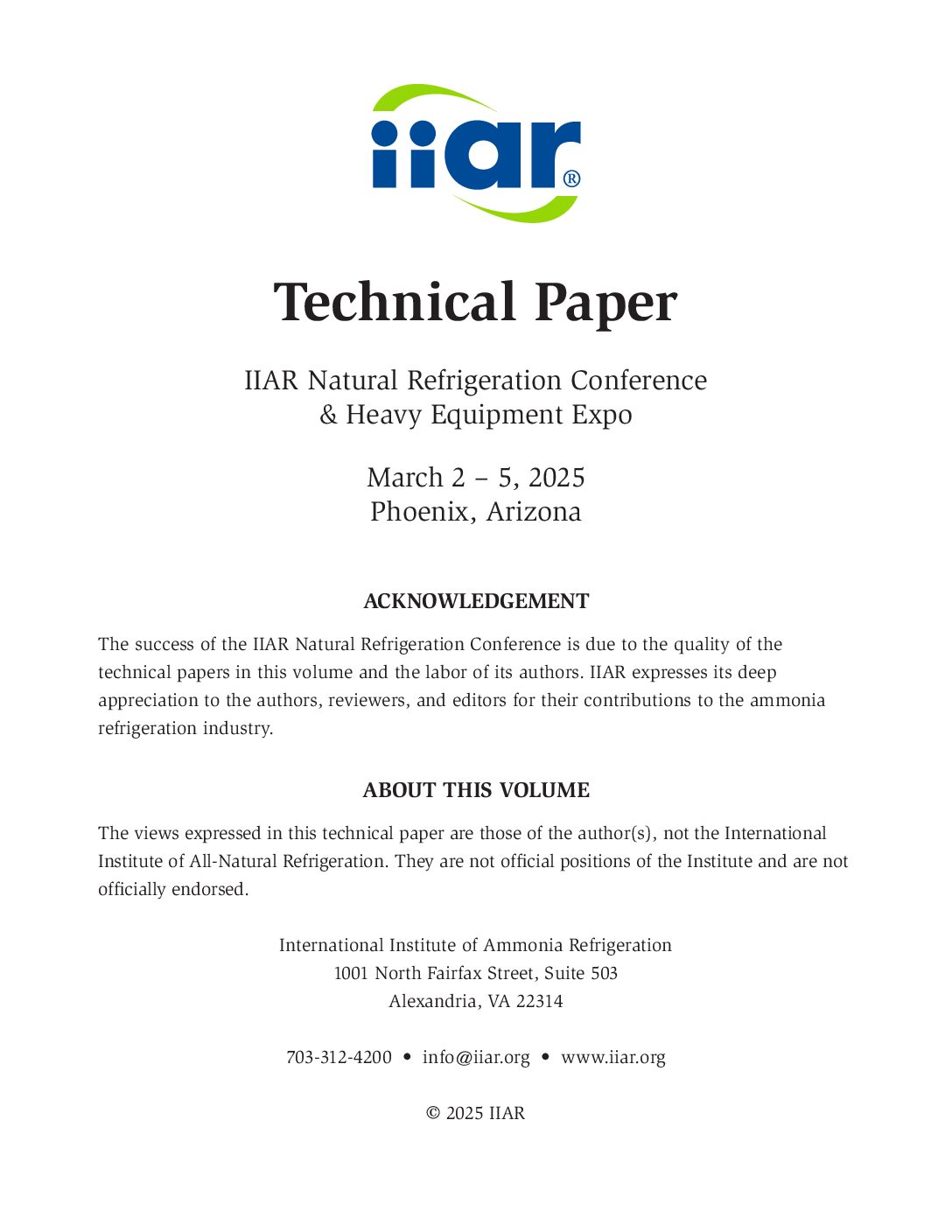
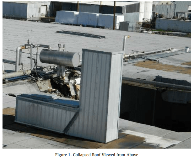
In December 2016, a roof collapse resulted in the release of approximately 24,000 lbs. of ammonia. Two (2) ceiling-suspended evaporators were hung from the roof and fell to the ground when the structure collapsed. Figures 1 and 2 show the collapsed roof and an ammonia surge drum.
Incident Description
During a heavy rainstorm, the roof over a cold storage room collapsed. Two (2) ceiling-suspended evaporator coils fell with the roof, breaking the piping between the roof-mounted accumulator and the two coils. Additionally, a large water pipe broke and flooded the room. The facility was evacuated, and first responders were notified.
First responders arrived on scene and shut off power and water to the facility. The king valve was closed by the Hazmat team and no further action was taken due to structural concerns. Ammonia levels inside the facility were monitored until it was determined that the leak was no longer active.
Release Calculation
The system inventory prior to the release was 28,000 lbs. After the release, an ammonia supply company came on-site to remove the remaining ammonia inventory from the system. The amount removed was approximately 3,705 lbs. Therefore, the amount released was calculated by subtracting 3,705 lbs. from the initial inventory of 28,000 lbs.
Ammonia Released = 28,000 lb – 3,705 lb = 24,295 lb
Significance
IIAR 2-2021 §6.2.2 states that “Where piping is supported by the floor, roof, or ceiling structure, the structure or foundation supporting the piping shall be designed to support the expected static and dynamic loads, including seismic loads. Foundations and supports shall be in accordance with the building code.”1
Insufficient roof drainage appears to be a contributing factor to the roof collapse. While it is unknown whether the roof structure was designed in accordance with the Building Code at the time it was installed, this incident illustrates the importance of monitoring the building structure and foundation. Even if a building is designed to code, decades of deterioration may result in a sudden collapse if not monitored and addressed.
Arc Flash in a Solenoid Valve
Summary
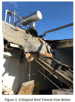
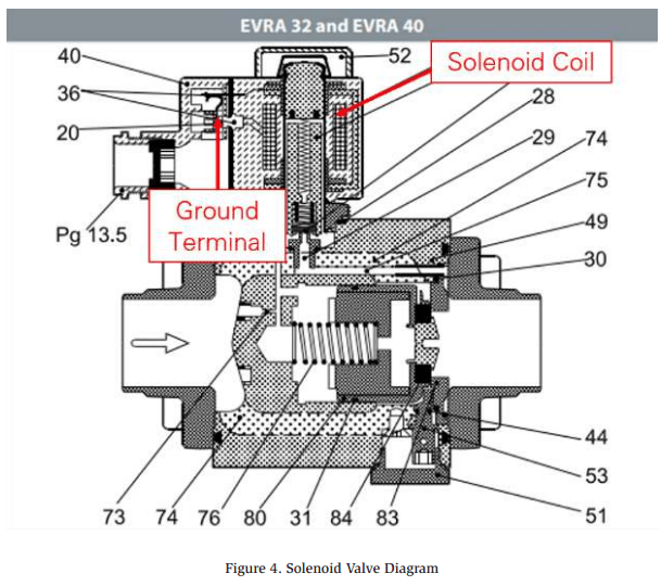
In September 2022, a solenoid coil grounded out against the plunger tube which burned a hole in the post of the valve as seen in Figure 3. This resulted in two injuries and the release of approximately 1,095 lbs. of ammonia.
Incident Description
Damage to the solenoid coil allowed the “live” coil to make contact with the “ground” terminal inside the valve. This sudden spike in voltage created an arc flash inside the valve. The arc flash burned a hole in the armature, which allowed the ammonia to escape through the valve. The locations of the solenoid coil and ground terminal in a solenoid valve are illustrated below in Figure 4.
Release Calculation
The size of the hole was measured in order to determine how much ammonia was released. Below are the assumptions and analysis from the release calculation
Assumptions
- The shape of the hole was assumed to be a rectangle
- Width: 3.06 mm
- Height: 0.47 mm
- Area: 1.4382 mm2 = 0.00223 in2
- Leak occurred for 370 minutes (7:56 pm – 2:06 am)
- Pressure during the leak was 37.9 psig (corresponding to 24ºF)
- Density of ammonia at 24ºF: 40.25 lb/ft3
- Molecular weight of ammonia: 17.03 g/mol
- Height of liquid above the hole: 0 ft
Analysis
Dow Chemical Exposure Index Guide, 1st Edition – Equation 2B (Page 12)
Significance
The root cause of the release was determined to be a failure/malfunction of the valve. Even when a system is well-maintained, mechanical failures can, and do, happen. Facilities should consider the location of valve groups in the event that a malfunction were to occur.
For example, evaporator valve groups are occasionally installed inside refrigerated spaces next to evaporator coils. If one of those valves malfunctions and causes a release, the ammonia would release indoors where employees may be exposed. Furthermore, accessing the isolation valves to mitigate the leak may be difficult. Valve groups located extremely high, or above stacked pallets/products may not be accessible with a lift or ladder in order to stop the leak. Ammonia refrigeration facilities should consider relocating valve groups from inside refrigerated spaces to the roof where they are more accessible during a leak.
Auto-Purger
Summary
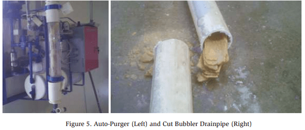
In September 2012, the rupture of an auto-purger bubbler resulted in two injuries, one of which was permanent and disabling. The root causes were determined to be a buildup of scale inside the bubbler, and failure to follow proper maintenance/ operating procedures.
Incident Description
Water & mineral deposits were collected in the drain line of the auto-purger which eventually prevented water from draining freely from the bubbler (See Figure 5). As a result, water began to escape from the top of the bubbler where the ¼” vent is located.
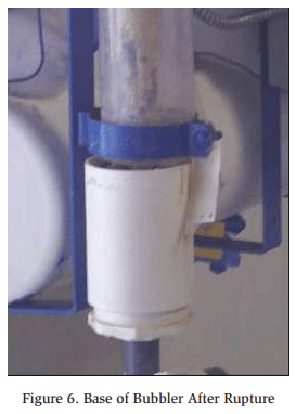
The two operators responsible for troubleshooting the situation failed to isolate and pump down the auto-purger before performing work. Instead, the vent hole was plugged, but the scale buildup in the drainpipe was not discovered or addressed. Since the water could no longer drain from the bubbler, the pressure rose when the auto-purger went through its normal purge cycle, and the bubbler ruptured (Figure 6). Both operators were standing near the bubbler and were splashed in the face with aqueous ammonia.
Significance
With further training regarding auto-purger operation and maintenance procedures, it is likely that the operators could have determined the root cause and avoided the incident altogether. Based on the approach taken to address the water leak, it can be assumed that the operators were not aware that the hole they plugged was a necessary vent port for proper drainage. Furthermore, if the auto-purger had been isolated and pumped down before performing work, the bubbler would not have over-pressurized while the operators were addressing the water leak.
This incident illustrates the importance of ensuring personnel are equipped with sufficient knowledge of a component to perform work safely. The auto-purger design is complicated and is hard to grasp intuitively. This is an instance where written operating procedures can be valuable both for training purposes and for guidance while performing work on the system.
Falling Ice Breaks Pipe
Summary
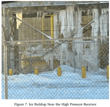
In December 2022, a falling piece of ice broke off a ¾” ammonia charging connection on a high pressure receiver. This resulted in the release of approximately 2,375 lbs. of ammonia. The amount of ice buildup around the high pressure receiver can be seen below in Figure 7.
Incident Description
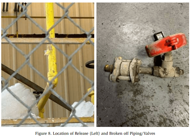
Extreme weather conditions resulted in excessive ice buildup under the condenser platform. The high pressure receiver was located under the condenser platform, where it was susceptible to falling ice. A portion of the ice fell onto a ¾” nipple associated with the high pressure receiver, shearing it off upstream of the charging connection check valve (See Figure 8).
The facility quickly responded by closing isolation valves on both the high pressure receiver and the thermosyphon vessel in order to isolate the leak.
Release Calculation
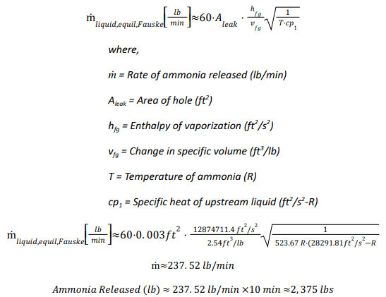
Due to the nature of the release, flash gas developed as the liquid ammonia leaked out of the broken pipe. Therefore, the release calculation was performed as follows which accounted for both liquid ammonia and the resulting flash gas:
Analysis
IIAR Technical Papers, 30th Annual Meeting (2008), Tech Paper 7, Estimating Refrigerant Release Quantities, Fauske Model, Equation 10.
Significance
Falling ice has the potential to both damage ammonia equipment, and cause injury to employees. While extreme weather conditions cannot be helped, ice buildup should be monitored and removed if the need arises.
Band Saw to a Live Line
Summary
In October 2021, a contractor accidentally cut into a live ammonia pipe, resulting in the release of approximately 419 lbs. of ammonia. Due to a general lack of labeling, the live pipe was confused for the decommissioned pipe that was intended to be cut out of the system.
Incident Description
A contractor was performing work on the refrigeration system in the machinery room. One of the pipes in the machinery room was scheduled to be removed as a part of a system renovation.
The contractor cut into the wrong pipe with a band saw which happened to be a live 1-½” thermosyphon return (TSR) line. The contractor was standing on a ladder at the time and was luckily able to escape without being injured. The machinery room ventilation system was turned on and a portion of the system was isolated from outside the machinery room.
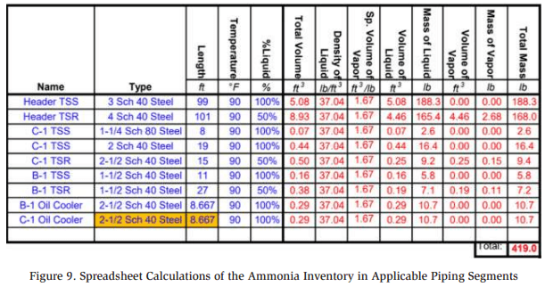
Release Calculation The amount of ammonia released was calculated by determining how much ammonia is normally contained in the thermosyphon piping. Based on the pipe diameters, lengths of piping, temperature of ammonia, and percent liquid, the total amount of ammonia inside the associated thermosyphon piping was calculated to be 419 lbs. as shown in Figure 9.
Significance
Pipe labeling is extremely important and can help prevent an accidental ammonia release. Equally important is developing detailed decommissioning procedures. A detailed procedure should clearly identify which pipes need to be cut from the system, nd instructions to tag these pipes and ensure they are pumped down completely.
It should be noted that the contractors were able to greatly reduce the amount of ammonia released by isolating a segment of the system from outside the machinery room. This was made possible by having accurate P&IDs to reference. Good documentation and labeling are often underestimated in their value. This incident illustrates the importance of both of these Process Safety Management cornerstones.
Brass Plug
Summary
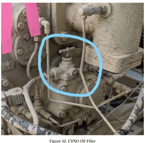
In July 2020, the installation of a brass plug in an ammonia refrigeration system resulted in a release of approximately 100-300 lbs. of ammonia. Due to the corrosive nature of ammonia on brass, the plug developed a leak due to corrosion.
Incident Description
A brass plug was installed on a CUNO oil filter (See Figure 10) several years prior. Over time, the ammonia ate away at the brass until the plug failed, releasing an ammonia/oil mixture. An anonymous person called 911 to report the smell of ammonia.
Release Calculation
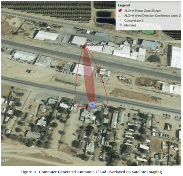
The release generated a concentration of 20 ppm at a nearby mini mart which was located approximately 580 ft from the leak. The weather conditions at the time of the release were input into the modeling software ALOHA:
- Wind Speed: 7 mph
- Cloud Cover: 30%
- Ambient Temperature: 99°F
- Relative Humidity: 18%
- Wind Direction: Directly towards the mini mart
Using the software which generated the image in Figure 11, it was determined that an ammonia release rate of 0.935 lbs./min would result in an ammonia concentration of 20 ppm at the mini mart. The ammonia release lasted approximately 307 minutes, and the amount released is calculated below.
Ammonia Released (lb) = 0.935 lbs./min x 307 min = 287.045 lbs. ≈ 290 lbs.
The incident investigation report notes the following regarding the release calculation:
“The release calculation is a conservatively high estimate with standard assumptions in order to obtain a constant release rate and therefore is not to be construed as exact. Both the nature of the oil/ammonia release and the cycling of the compressor make it impossible to know how much was released.”
Significance
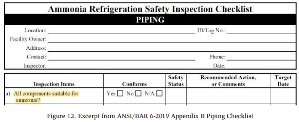
Brass, copper, and galvanized steel will corrode in the presence of ammonia as demonstrated by this event. Operators and contractors should take care to ensure that only compatible materials are used in ammonia systems. The inspection checklist in ANSI/IIAR 6-2019 Appendix B2 can be a helpful reminder to inspect materials used in the system and ensure their compatibility (See Figure 12).
Brine Chiller
Summary
In October 2017, an ammonia release inside a machinery room resulted in the deaths of three people – two city workers and one refrigeration technician. A pinhole leak developed in a shell and tube brine chiller, which allowed ammonia to leak into the brine solution. The leak was discovered, but due to a lack of refrigeration knowledge, the root cause was not properly addressed. This allowed a larger leak to occur later that day while personnel were present in the machinery room. Click here for a detailed video of the event.
Incident Description
The ammonia refrigeration system was used to cool a brine solution. The brine circulated and chilled two ice rinks installed at the facility. Corrosion in a shell and tube brine chiller caused the formation of a pinhole in one of the tubes. Ammonia leaked through the pinhole and began to mix with the brine solution. Some of the brine solution is stored in tanks that are open to the atmosphere. Once the ammonia reached these tanks, the vapor triggered the ammonia detectors which activated an alarm and notified the fire department and security company.
Two firefighters and one city worker entered the machinery room wearing SCBAs (self-contained breathing apparatus). Using hand-held ammonia detectors, the ammonia concentration was measured at 300 ppm. The leaking chiller was isolated on the ammonia side, and the ammonia refrigeration system was shut down. Parts of the brine system were shut down and the machinery room was vented of ammonia vapor. Eventually, the ammonia levels in the machinery room dropped to 50 ppm. Unbeknownst to the responders, the ammonia continued to leak into the brine solution, even after the chiller was isolated.
In order to prevent the ice rinks from melting, it was decided that the ammonia compressors should be turned back on. It was soon discovered that the oil in the compressors had been contaminated with brine which prevented the compressors from starting. A refrigeration contractor was called to replace the oil in the compressors.
Prior to the arrival of the contractor, the ammonia alarm was placed into silent mode. When the contractor and two city workers entered the machinery room, they were not wearing PPE (personal protective equipment), or equipped with ammonia detectors.
While the oil was being changed, the pressure in the brine piping began to rise due to the increasing amounts of ammonia inside the brine system. One of the couplings in the brine piping was unable to withstand the pressure buildup, causing it to separate and spray the three workers with ammonia and brine. The resulting ammonia concentration in the machinery room was not survivable and resulted in the deaths of the contractor and two city workers.
Significance
Many steps were taken without sufficient knowledge which resulted in this tragedy. If the first responders had been advised by a knowledgeable refrigeration expert, they would have been able to properly isolate and pump down the shell and tube chiller. Once the shell and tube chiller was empty of both ammonia and brine, it could have been completely isolated and the leak mitigated. This incident also illustrates the deadly toxicity of ammonia and how quickly a situation can escalate. Proper PPE and training can make the difference between escaping with your life or never making it back home.
Compressor Suction Gasket
Summary
In June 2020, the failure of a bolt on the strainer cap for a compressor led to the release of 5,461 lbs. of ammonia. One of the four bolts for the strainer cap had been broken for years. A second bolt broke during the incident as the compressor suction gasket failed.
Incident Description
When the compressor HSS gasket failed, low pressure ammonia vapor was released into the machinery room. The ammonia detectors in the room began to alarm and the ventilation fans were automatically activated. An operator remotely shut down the compressors inside the machinery room and left the condensers running.
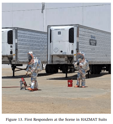
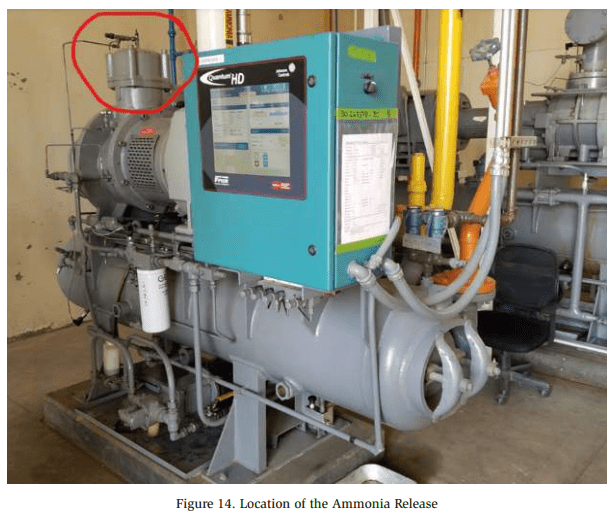
Notifications of the leak were made, and the fire department, a refrigeration contractor, and a Hazmat team arrived on site. The ammonia detector concentration display was visible from outside the machinery room by using binoculars. The detector displayed an ammonia concentration of 800 ppm, which was the highest concentration it was capable of displaying. The Hazmat team donned Level A Hazmat suits (Figure 13) and entered the machinery room where they recorded a peak ammonia concentration of 8,300 ppm.
At the time, the source of the ammonia leak was unknown. Therefore, the king valve was closed along with several valves associated with the auto-purger. Eventually, the source of the leak was discovered at a compressor high stage suction strainer (See Figure 14). The compressor suction and discharge valves were isolated, and the leak dissipated.
Release Calculation
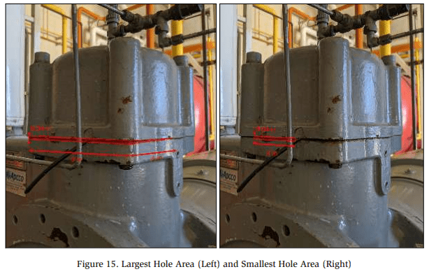
The release calculation was complex due to the unusual hole shape and size. The ammonia release calculation states the following:
“A gasket inside the strainer tore and approximately four inches of the gasket was forced out of the strainer at the time of the release. Due to the nature of the hole, two area calculations were performed: one area calculation assuming the largest possible hole area, and another assuming the smallest possible hole area.”
Figure 15 illustrates the possible hole areas through which the ammonia leaked. Figure 15 illustrates the possible hole areas through which the ammonia leaked.
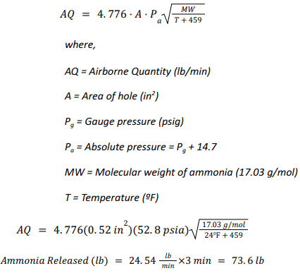
A release calculation was also performed for three separate phases of the release. Each of the phases represents a different change in pressure of the ammonia vapor.
- Phase 1 – 38 psig – Prior to all compressors being shut down (3 min)
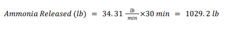
- Phase 2 – 38 to 80 psig – System equalization and increase in suction
pressure (30 min) - Phase 3 – 80 psig to 7 psig – Consistent decrease in suction pressure (267 min)
The pressure changes during Phase 2 and Phase 3 were assumed to be constant (linear). Calculations were performed using the average pressure during each phase.
Large Hole Size – Phase 1 Analysis
Dow Chemical Exposure Index Guide, 1st Edition – Equation 1B (Page 11)
Large Hole Size – Phase 2 Analysis
Using the same equation as above, the amount released during this phase was calculated using an average pressure of 59 psig.
Large Hole Size – Phase 3 Analysis
Using the same equation as above, the amount released during this phase was calculated using an average pressure of 43.5 psig.
Large Hole Size – Total Ammonia Released
By adding together the amount of ammonia released in each of the three phases, the total amount released for the large hole size was calculated to be 8,352.7 lbs.
Small Hole Size – Total Ammonia Released
Using the same analysis above, the hole size was changed and the same calculations were performed. The total ammonia released for the smaller hole size was calculated to be 2,570.1 lbs
![]()
The reported quantity released was an average of the amount calculated for the large hole size and the small hole size, which was approximately 5,461 lbs. of ammonia.
Significance
The cause of the release appeared to be the first broken bolt on the suction strainer cap. The mechanical integrity records were reviewed in order to determine when the bolt broke, and whether the inspecting contractor identified it.
A mechanical integrity inspection report from early 2020 identified the broken bolt and recommended that it be replaced. However, the report summary also indicated that “no issues were found,” which was misleading. Reportedly, the inspecting contractor did not verbally communicate the need to replace the broken bolt to the facility.
In the end, it was determined that the facility did not properly review the mechanical integrity report when it was delivered. Although inspection reports may sometimes be confusing or contain an overwhelming amount of information, it is important to ensure each recommendation is reviewed and addressed accordingly.
Contractor Error and Coil Failure
Summary
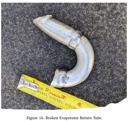
In August 2022, hydrostatic expansion occurred inside an improperly isolated evaporator coil, resulting in a release of approximately 230 lbs. of ammonia. The leak occurred when one of the return tubes of the evaporator coil broke due to the overpressurization (See Figure 16).
Incident Description
The evaporator coil (Coil 3) was recently replaced and the other two coils in the room (Coils 1-2) were left unchanged. The Coil 3 had been installed and pressure tested but was scheduled to be commissioned after the insulation contractor could complete the piping.
Days before the leak, the room was needed for product cooling. Therefore, the new evaporator liquid isolation valve was closed, and the suction return valve was left slightly open to allow ammonia from the pressure test to escape. The zone was turned on with Coils 1-2 operating
Over several days, ammonia vapor entered from the suction pipe shared with Coils 1-2. It is suspected that the vapor condensed inside the coil over time. The night of the incident, the zone went into a water defrost cycle. This raised the temperature of the coils and the liquid/vapor mix in Coil 3 rapidly expanded. Since the suction valve was slightly cracked, the ammonia could not return fast enough. This built excessive pressure, causing the coil return tube to break at the location indicated in Figure 17.

Release Calculation
The release calculation was performed under the conservative assumption that at the time of the leak, Coil 3 was completely full of liquid. It was also assumed that no additional ammonia entered the coil through the suction isolation valve.
Based on these assumptions, the amount of ammonia released was calculated using the internal volume of the evaporator. Assuming the coil was completely filled with liquid, and knowing the internal volume of the coil was 5.76 cubic feet, this corresponds to 230.2 lbs. of liquid ammonia.
Significance
The contributing factors to the release appear to be a contractor error, and impatience of the facility to start cooling the room. An error was made by the contractor in not opening the suction valve enough to allow for hydrostatic expansion to occur. Reportedly, the construction crew did not consult with the refrigeration service or engineering department before adjusting the valves on the evaporator after the pressure test. Had they obtained instructions or been supervised by another department, the suction valve would have been left fully open, or fully closed after ensuring the evaporator was empty of ammonia.
The premature cooling of the room where Coil 3 was located may have been another contributing factor to the release. It is unknown whether the installing contractor was consulted before Coils 1-2 were turned on.
This incident illustrates the danger of hydrostatic expansion and the type of damage that can be caused. In order to prevent liquid ammonia from being trapped in an ammonia system, facilities should ensure that vessels are not filled beyond 85%, and purge valves are installed at valve groups where the automatic trapping of liquid can occur.
Evaporator Arc Flash
Summary
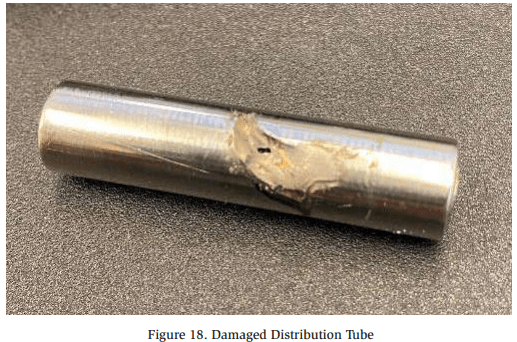
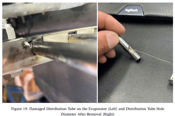
In June 2023, the vibration of an evaporator over an extended period of time allowed exposed electrical wiring to cause an arc flash that ruptured a distribution tube (See electrical wiring to cause an arc flash that ruptured a distribution tube (See Figure 18). This resulted in two (2) injuries and a release of approximately 11 lbs. of ammonia.
Incident Description
The direct-expansion evaporator was equipped with an electric heater defrost pad. The associated electrical wiring insulator wore through due to the vibration of the evaporator over an extended period of time. The exposed electrical wiring came into contact with the TX valve distribution tubes, causing an arc flash that ruptured a distribution tube and created the damage shown below in Figure 19.
Release Calculation
The release calculation for this release was relatively simple thanks to the circular shape of the hole. Based on a hole diameter of 0.029 inches, an ammonia temperature of 17°F, and the length of the release being approximately 407 minutes, the total amount of ammonia released was calculated to be 11 lbs.
Significance
Maintenance and upkeep on electrical components might often be overlooked at a facility. Ensuring that wire insulators are in good condition can prevent an arc flash as seen here, and corrosion/deterioration of the exposed wire.
Additionally, the General System Checklist in Appendix B of ANSI/IIAR 6-2019 includes the following inspection item regarding electrical components: “Covers are securely fastened on all electrical panels and junction boxes?”3 Facilities should ensure that electrical components associated with, or near ammonia refrigeration equipment are in good condition and still properly installed.
High Pressure Receiver Relief Valve Termination
Summary
In July 2017, the termination of a relief valve to the atmosphere resulted in a release of approximately 1,500 lbs. of ammonia, and four personnel injuries. Proper operating procedures were not followed during a seasonal startup of the ammonia system. Several mistakes were made which resulted in the high pressure receiver over-pressurizing and the relief valve lifting.
Incident Description
The ammonia refrigeration system had been previously shut down for the off-season at this cold storage facility. In preparation for the upcoming season, the refrigeration system was turned back on, but operating procedures were not followed during the start-up process.
During start-up, the condenser fans were not turned on which allowed the discharge pressure to rise. When the discharge pressure reached the high pressure cutout setpoint, the compressor did not shut down as intended. The compressor controls had been left in “local” mode which allowed the compressor to bypass the high pressure cutout shutdown. Consequently, the discharge pressure continued to rise until the high pressure receiver relief valve lifted at 250 psig.
The relief valve terminated to the atmosphere above the facility roof. The termination point exceeded the requirement of being located at least 7.25 feet above the roof, However, due to the close proximity of public receptors (Shown in Figure 20), the following recommendation was made following the release:
“Deliberate consideration should be given to installing an ammonia diffusion tank because of facility location to the freeway and local businesses.”
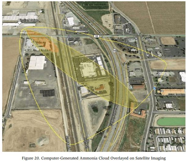
Although the facility was not required to install a diffusion tank per the applicable RAGAGEP, it would have significantly reduced the chance of employee injury and exposure to nearby receptors. In some instances, diffusion tanks can be a prudent defensive strategy in containing ammonia vapor during a release.
Release Calculation
The release occurred in two (2) phases: Phase 1 is the period when the relief valve was relieving at full capacity; Phase 2 is the period when the relief valve had mostly closed and was “seeping” ammonia. During Phase 2, it was assumed that the relief valve relieved 10% of its full capacity. The amount of ammonia released during each phase is calculated below:
Phase 1 Analysis
Phase 2 Analysis
![]()
Total Ammonia Released

The calculations indicated that approximately 1,500 lbs. of ammonia was released from the relief valve.
Significance
This release illustrates the importance of training personnel on the operating procedures for start-up, shutdown, and other phases of operation. The following recommendation was made regarding the release, and training of personnel:
“Current employees have not been adequately trained in an overview of the refrigeration system or its operation. Ensure applicable employees are trained in: (1) Overview of the process, including its operating limits and consequences of deviation (2) Operating Procedures (3) Emergency Response.”
If the proper procedures had been followed, the condenser fans would have been operating, and the compressor switched out of “local” mode. Had this been the case, it is likely that the discharge pressure would not have climbed as high as it did, and the relief valve would not have lifted.
Human error is an inescapable reality of the world we live in. Everyone makes mistakes, but proper training and operating procedures can help reduce the frequency and severity of a mistake when it happens.
Hydraulic Shock
Summary
In August 2010, hydraulic shock in a suction pipe resulted in a release of 32,000 lbs. of ammonia. Over 150 injuries were reported from the ammonia release. The sequence leading to any release is complicated, and this event was no exception. The root cause was determined to be human error with respect to the computer control system. For a deep dive into the incident, go to https://youtu.be/_icf-5uoZbc?si=gM0hBhfunCcRQz2W to watch the Chemical Safety Board’s recreation and explanation of the event.
Incident Description
Select evaporators were in the process of hot gas defrost when the facility lost power for several hours. Once power was restored, the refrigeration system automatically resumed the defrosting process. Using the computer control system, a programming error caused the defrost cycle to be interrupted and refrigeration mode initiated when an operator cleared an alarm related to the power failure. Cold liquid ammonia was sent to the defrosting evaporator, containing warm vapor ammonia. The combination of the hot gas and cold liquid resulted in rapid depressurization and two pipe ruptures, including a 12″ pipe located on the roof of the facility (Shown in Figure 21).
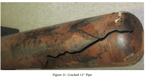
The ammonia cloud was large enough to impact a nearby worksite where eight hundred contractors were working outside. Reportedly, 153 people were exposed to ammonia. Thirty-two of those were hospitalized, and four were admitted to an intensive care unit.
Significance
It is essential that the defrost system be programmed with interlocks to ensure cold liquid ammonia and hot gas remain isolated when transitioning to or from defrost. Additionally, sufficient training in computer controls is crucial for ensuring the safe operation of an ammonia refrigeration system. Training should include procedures for restarting a component after a power failure or normal shutdown.
Pinhole Leak
Summary
In September 2016, the development of a small hole in the wall of an ammonia suction pipe resulted in the release of 15 lbs. of ammonia. Neglected insulation breaches allowed moisture to accumulate on carbon steel piping. This resulted in corrosion and eventually, a pinhole developed in the wall of the pipe.
Release Calculation
The release calculation was performed with the following assumptions:
- Leak Duration: 40 minutes
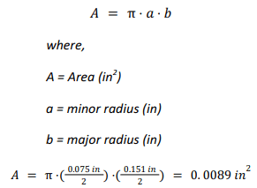
- Shape of hole was assumed to be an ellipse
- Minor radius = 0.0375 in
- Major radius = 0.0755 in
- Pressure: 33.5 PSIG (corresponding to 20ºF)
- Molecular Weight of Ammonia: 17.03 g/mol
- Pipe insulation did not mitigate the leak
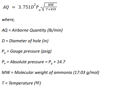
A challenging aspect of the release calculation was the shape of the hole. As stated above, the hole was assumed to be in the shape of an ellipse, which is more complicated to calculate compared to a perfect circle. The amount of vapor released from a circular hole was calculated as follows:
Vapor Release
Dow Chemical Exposure Index Guide, 1st Edition – Equation 1B (Page 11)
Adjusting the equation to allow for an ellipse-shaped hole, rather than a circle results in:
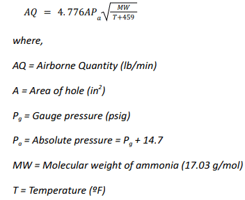
Area of an Ellipse
Airborne Quan Airborne Quantitytity
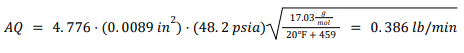
Total Ammonia Released
Significance
IIAR 6-2019 §11.1(b) states “Visually inspect for damage or moisture incursion in insulation (i.e., dampness, condensation, frost, ice buildup)”4 . Damaged or saturated insulation allows moisture to corrode the piping underneath. This pinhole leak appeared to be directly caused by corrosion under insulation (CUI) and possibly could have been prevented by quickly addressing saturated insulation. Facilities should ensure they have implemented a comprehensive pipe inspection and maintenance program to ensure CUI is caught and addressed before it’s too late.
Nurse Tank Mechanical Failure
Summary
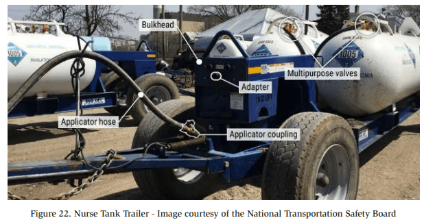
In April 2019, the mechanical failure of an applicator coupling resulted in a release of approximately 3,640 lbs. of ammonia and 83 injuries. The release occurred from a nurse tank being transported near a residential area
Incident Description
A tractor was transporting a pair of two-ton nurse tanks filled with ammonia when an applicator coupling on the tank became unscrewed. Figure 22 below displays a typical applicator coupling used for transporting nurse tanks. Due to the foggy weather, the ammonia did not dissipate into the atmosphere but stayed low to the ground, exposing many people in the nearby town.
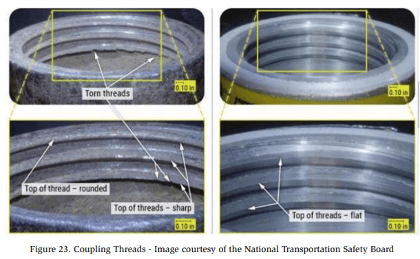
After further investigation, it was discovered that the threads of the coupling had deteriorated from age and corrosion (See Figure 23). This was determined to be the underlying cause of the coupling unscrewing during transportation.
During transportation, the isolation valve between the nurse tank and the applicator hose connection was left open. When the applicator hose disconnected from the tank, the ammonia release began. The nurse tanks were equipped with excess flow valves which were designed to close automatically to prevent a leak of this nature. However, the excess flow valves would only close if the flow rate of ammonia exceeded 42 gpm, and the maximum flow rate during the release never exceeded 25 gpm.
Significance
This incident instigated several changes to Illinois state law, and manufacturer design of nurse tank configurations. The state of Illinois now requires that “all nurse tank valves be closed during transport on public rights of way.”5 This is to ensure that if an applicator hose detached in the future, the ammonia would not be able to leak out of the tank.
In order to address the problem with the excess flow valves, Conserv FS, the company that assembled the two nurse tanks into a tank unit, prohibited the configuration of the tank unit in question. The configuration of the tank unit involved in this incident consisted of “two source tanks with a single delivery line.”6 The single delivery line reduced the ammonia flow rate below the rate at which the excess flow valves would close. “Conserve FS began reconfiguring nurse tanks to discharge singularly from each tank regardless of the number of tanks mounted on a trailer.”7
A final item regarding this ammonia release is the perfect storm that occurred in regard to weather conditions. The presence and location of fog at the time of the release caused the ammonia cloud to stay low to the ground where it spread throughout the residential area. While the weather could not be anticipated or changed, this incident serves as a reminder that weather can play an important role in the events of an ammonia release. Ammonia facilities should consider weather events that can be anticipated and plan accordingly. Shifting wind directions can be addressed by installing windsocks, and excess sun exposure or rain can be managed by erecting roofs and shelters for ammonia equipment.
Intercooler Relief Valve Termination
Summary
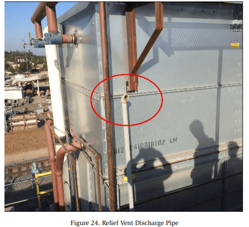
In September 2014, the termination of a relief valve to the atmosphere resulted in a release of approximately 2,700 lbs. of ammonia. During the release, a roof-mounted exhaust fan pulled ammonia vapor into a highly populated room in the processing facility which exposed thirty-four employees to ammonia. The ammonia was released from the relief vent discharge pipe circled in Figure 24.
Incident Description
One of the relief valves installed on the Intercooler lifted when an operator repeatedly attempted to start a booster compressor when the intercooler was in a high level condition. It is estimated that the relief valve remained open for between 5 and 15 minutes. The relief vent pipe terminated approximately two feet above the roof near four exhaust fans for a processing room. At the time of the release, one of the fans was operating while the other three were off. The fans that were off functioned as make-up air openings and allowed some of the ammonia vapor to be pulled into the building.
Release Calculation
At the time of the relief valve lifting, the intercooler was in a high level condition and full of liquid. Based on the high liquid level, it is possible that liquid ammonia was released through the relief valve. Therefore, calculations were performed for the scenario of a vapor-only release, a liquid-only release, and an average of the two.
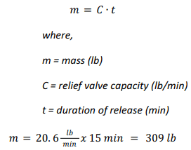
Vapor-Only Calculation
Calculating the amount of ammonia vapor released was done by utilizing the rated capacity of the relief valve. The Intercooler was equipped with a Cyrus Shank 803 150 psig relief valve which has a rated capacity of 26.7 lb/min (air), which is 20.6 lb/ min (ammonia):
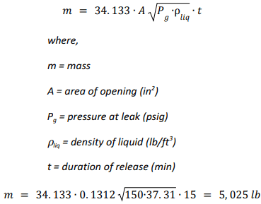
Liquid-Only Calculation
To assess the liquid-only release scenario, the equation below was adapted from the Dow Chemical Exposure Index Guide, 1st Edition.
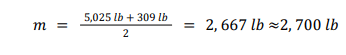
50% Liquid, 50% Vapor Calculation
The liquid/vapor mixture calculation was performed by simply averaging the two calculations.
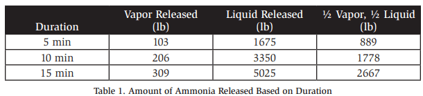
As many factors to this release were unknown, additional calculations were performed and summarized in the table below. The release calculation report concluded that the release was approximately 2,700 lbs. but included Table 1 below to demonstrate the various possibilities.
Significance
Many errors were made that eventually resulted in this incident. The configuration of the relief valve termination piping, however, is the one worth examining.
IIAR 9-2020 §7.4.2.1 states that “The termination of pressure relief device discharge piping relieving to the atmosphere shall not be less than 15 ft (4.6 m) above grade and not less than 20 ft (6.1 m) from windows, ventilation intakes, or exits.”8
Additionally, §7.4.2.1 addresses the height of discharge termination points above roofs. “The discharge termination from pressure relief devices relieving to atmosphere shall not be less than 7.25 ft (2.2 m) above a roof that is occupied solely during service and inspection. Where a higher adjacent roof level is within 20 ft (6.1 m) horizontal distance from the relief discharge, the discharge termination shall not be less than 7.25 ft (2.2 m) above the height of the higher adjacent roof.”9
The height and location of the relief vent termination point was a contributing factor to the employee ammonia exposure. If the termination point had been 20 feet away from the ventilation intake and 7.25 feet above the adjacent roof, ammonia vapor would not likely have been pulled into the building through the exhaust system.
Service Valve Hole
Summary
In June 2016, a hole developed in the nipple of a ½” service valve (See Figure 25), resulting in a release of 1,224 lbs. of ammonia. The service valve, installed on a liquid transfer vessel, began leaking liquid ammonia into the machinery room
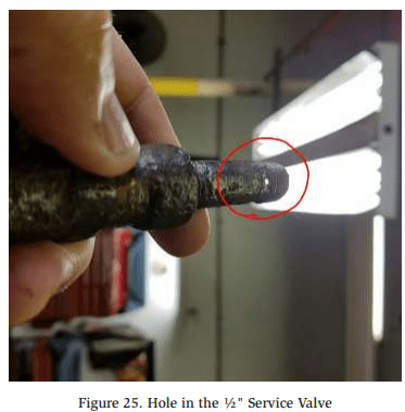
Incident Description
Long term, chronic corrosion caused a 1.5 mm hole to develop in the nipple of the 1/2″ service valve on a Liquid Transfer Vessel. Click here to see a video of the ammonia leak in action.
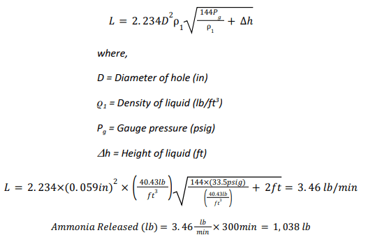
Release Calculation
The leak occurred in two (2) phases which were analyzed independently. Phase 1 of the leak spans from the beginning of the leak to the time when the liquid transfer vessel was isolated. Phase 2 of the leak spans from the isolation of the liquid transfer vessel to the end of the leak. The duration of Phase 1 was approximately 5 hours, and the duration of Phase 2 was approximately 9 hours.
The amount of ammonia released during Phase 1 was calculated to be 1,038 lbs., and the amount calculated during Phase 2 was 186 lbs. Excerpts from the calculations are shown below.
Phase 1 Analysis
Dow Chemical Exposure Index Guide, 1st Edition – Equation 2B (Page 12)
Phase 2 Analysis
LTV-1 Dimensions:
- Diameter: 24″
- Length: 3′-6″
- Shell Volume = 6.265 ft3
- Head Volume = 1.0 ft3
- Total Volume = 8.265 ft3
Quantity of Liquid Ammonia in LTV-1 at the start of Phase 2
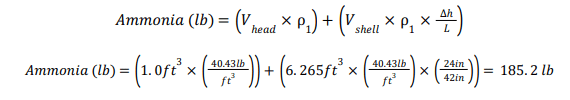
Quantity of Vapor Ammonia in LTV-1 at the start of Phase 2
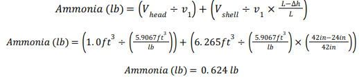
Total Quantity of Ammonia in LTV-1 at the Start of Phase 2
![]()
Total Ammonia Released
![]()
Significance
ANSI/IIAR 6-2019 §10.1(b) & §11.1(a) instructs to “Visually inspect metal surfaces for pitting or surface damage”10. As illustrated by this incident, the formation of pits can result in a serious ammonia leak. Liquid transfer vessels and piping are particularly susceptible to corrosion and pitting due to the constant freezing and thawing cycle of the piping and vessel. Annual inspections of pipe/vessel corrosion is an important aspect of a maintenance program and should not be neglected.
Service Valve Open to Atmosphere
Summary
In September 2023, a service valve left open to the atmosphere resulted in the release of ammonia when an operator opened a closed isolation valve. The reported amount of ammonia released in the final incident investigation report was 2-8 lbs.
Incident Description
An operator was performing maintenance on an evaporator valve group. He used the service valve to purge trapped ammonia within the valve group during maintenance. After maintenance was completed, the service valve was left open to the atmosphere and unattended for approximately one week (See Figure 26). Additionally, lockout/ tagout was not utilized on the valve group in question.
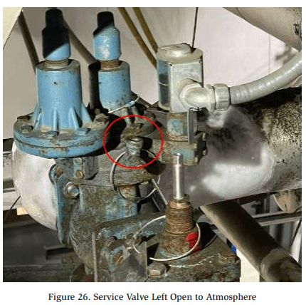
Approximately one week later, an operator was performing daily rounds and noticed that the temperature in one of the cold storage rooms was high. In order to lower the temperature in the room, he opened the liquid feed isolation valve for the valve group that had previously been isolated for maintenance. Upon opening the valve, he heard a hissing sound, so he quickly closed the valve again. Between the time that the isolation valve was opened and closed, ammonia escaped from the service valve.
Release Calculation
Three scenarios were considered for the release calculations based on the information available
Scenario 1
Scenario 1 was calculated off the basis that an ammonia reading of 86 ppm taken inside of one of the buildings in the facility. The dimensions of the building were measured using Google Earth, and the height of the building was estimated. This scenario resulted in a calculation of 2.8 lbs. of ammonia.
Scenario 2
Scenario 2 was calculated on the basis that the 1” liquid supply pipe was open for 15 seconds. Based on the internal diameter of the liquid pipe, this would have allowed approximately 225.9 lbs. of ammonia to enter the valve group before the liquid isolation valve was closed again. It was assumed that all of the liquid supplied to the valve group eventually leaked out of the open service valve. Therefore, this scenario calculated the amount of ammonia released to be 225.9 lbs.
Scenario 3
This scenario was calculated on the assumption that the ¼” service valve was partially open for 20 minutes. Assuming the valve was 20% open and vapor was releasing at a constant temperature, resulted in 8 lbs. of ammonia being released.
Significance
Many errors were made that eventually resulted in this incident. Most notably, the service valve open to the atmosphere should never have been left unattended. After use, the service valve should have been closed, and either plugged or capped.
Another error in this event was the failure to follow proper lockout/tagout (LOTO) procedure. LOTO is vital for ensuring clear communication between operators, contractors, and facility employees. This incident could have been much worse and possibly resulted in a death if circumstances were different.
Stress Cracking
Summary
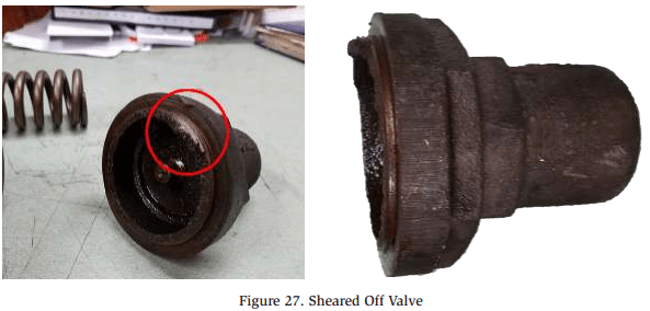
In August 2016, the sudden breaking of a valve on an ammonia pump resulted in the release of 34-284 lbs. of ammonia. The root cause was determined to be a stress crack that formed at the threads of a valve (See Figure 27), ultimately leading to the top of the valve shearing off.
Incident Description
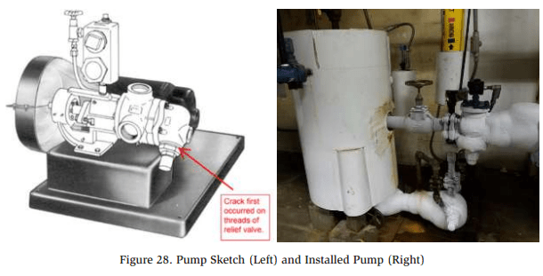
The ammonia refrigeration system at the food processing/cold storage plant was configured with a liquid transfer vessel and transfer pump shown below in Figure 28. The valve in question was located in the pump bypass piping.
Investigation into the incident revealed that the stress crack formed from years of frosting and thawing cycles. The cycles allowed water to freeze and expand, then contract as the ice melted. This phenomenon is commonly seen on roadways where freezing and thawing of water results in crack formation.
Release Calculation
Calculating the amount of ammonia released was dependent on the liquid level inside the Liquid Transfer Vessel when the failure occurred. At the time of the leak, a technician was able to quickly isolate the vessel. Therefore, the calculation assumed that no additional ammonia entered the vessel once the leak began. However, the initial liquid level in the vessel at the start of the leak was unknown, so multiple calculations were performed.
Liquid Transfer Vessel Specifications
Orientation: Vertical
Diameter: 24″
Length: 3′-6″
NH3 @ 85% full: 284 lbs.
NH3 @ 10% full: 34 lbs.
The vessel would have contained 284 lbs. of ammonia at a maximum liquid level. At a minimum liquid level, it would have contained 34 lbs. Therefore, the release was reported as a range of 34-284 lbs. of ammonia.
Significance
IIAR 6-2019 §5.6.8 states that “Equipment and piping shall be kept free from excessive ice buildup.”11 Visual inspection of equipment is crucial for ensuring proper system maintenance. While a stress crack inside a valve may not be visible during daily rounds, special attention should be paid during maintenance activities to areas that experience frequent frosting and thawing. Corrosion and crack formation are often more likely to develop in these conditions, so liquid transfer vessels/pumps should be closely monitored.
Suction Regulator
Summary In May 2019, ammonia began leaking from a suction regulator installed on the roof of a facility. The incident resulted in seven reported injuries and one fatality. The leak calculations determined that approximately 12 lbs. of ammonia was released before the valve was isolated.
Incident Description
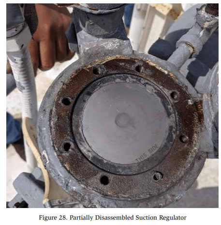
One of the eight bolts holding the suction regulator gasket broke. This caused a slit to open on the side of the gasket which allowed pressurized ammonia to escape. Facility employees smelled the ammonia and began to evacuate. When an ammonia contractor arrived on the scene, the King Valve was closed, and the leaking suction regulator was isolated and purged of residual ammonia.
The cause of the incident was determined to be an equipment malfunction of the suction regulator. The internal components of the valve had been inspected two months prior to the incident. Therefore, it is unlikely that inadequate maintenance is a contributing factor. Figure 28 shows the partially disassembled suction regulator with no indications of improper maintenance.
One of the employees was admitted to the hospital and later passed away. The employee was not directly exposed to the ammonia but had an underlying heart condition that was exacerbated by the event.
Release Calculation
The opening in the valve where the ammonia leak occurred was measured to be approximately ¾” wide by 1/64″ high. Using the calculation basis from Dow’s Chemical Exposure Index Guide, First Edition, the amount of ammonia released in the 25 minute span was calculated to be approximately 12 lbs. This was based on the following criteria:
- Molecular Weight of Ammonia: 17.03 g/mol
- Temperature of Ammonia: 17°
- Area of the Hole: 0.012 in²
- Length of Release: 25 minutes
Significance
Even when maintenance tasks are performed at the proper frequency, mechanical failures can and do happen. Fortunately, the mechanical failure occurred on the low pressure side of the system where the amount of ammonia released was minimal.
It should be noted that even a small ammonia release was enough to be noticeable to the employees and initiate an evacuation. Facilities may wish to consider that panic often arises when an employee outside the realm of refrigeration smells ammonia. Excessive panic or slight ammonia exposure could be fatal to those with underlying health conditions. Thorough and frequent ammonia awareness training may help to put employees at ease, and ensure they are well-prepared when an evacuation is necessary.
Tarp vs. Fan vs. Coil
Summary
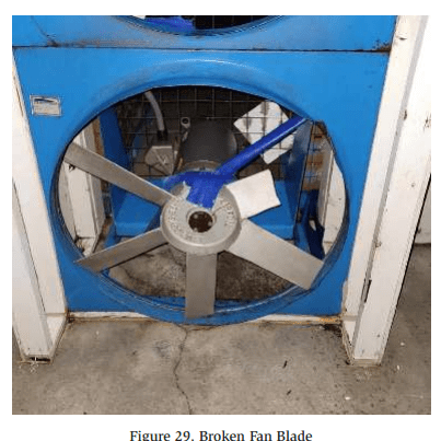
In May 2021, a three-inch strip of tarp was sucked into a lower bunker fan for a post cooler room. Two fan blades broke and flew into the bunker evaporator coil, resulting in a release of approximately 4,600 lbs. of ammonia.
Incident Description
The post cooler room is equipped with a bunker that contains two evaporator coils that are supplied by a single accumulator. The evaporator coils are installed above the fans that circulate air through the coils.
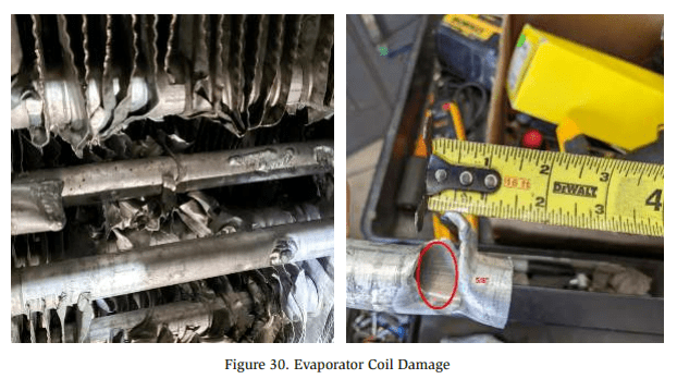
Inside the room, a small tarp is used to wrap product pallets to produce more efficient cooling. A small piece of tarp was able to slip through the fan guard and was sucked into the fan. Two of the fan blades broke (See Figure 29) and flew upwards into one of the bunker evaporator coils. The fan blades punctured two holes in the coil (See Figure 30) which caused the release.
Release Calculation
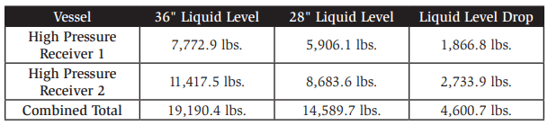
The amount of ammonia released from the system was calculated based on the normal operating level in the high pressure receivers. The system is equipped with two (2) high pressure receivers which are interconnected. The normal liquid level inside the two vessels is 36 inches. After the release, the liquid level in the high pressure receivers was measured at 28 inches. The table below illustrates the amount of ammonia released was estimated to be 4,600 lbs.
Significance
Even though fan guards were in place, this did not prevent the tarp from becoming stuck in the fan. The incident prompted a recommendation to either change the tarp size/design, or to improve the fan guard design in order to prevent the accident from recurring. Facilities should consider the proximity of stacked pallets to fans and ensure fan guarding is adequate.
Conclusion
The incidents contained in this paper offer a variety of lessons to learn from. Activities like performing routine inspections or providing in-depth operator training may be viewed by some as an unnecessary expense. However, the incidents above illustrate the importance of activities like these, and how they can be the determining factor in whether an ammonia leak is a minor occurrence, or a major catastrophe.
These historical incidents also illustrate a variety of strategies that were used to perform release calculations. From these incident investigations, it can be seen that performing release calculations is often a complicated process. In some cases, calculating the amount of ammonia released is a straight-forward process and produces accurate results. Other scenarios require a creative approach when information is lacking, and many factors have to be assumed.
We live in an imperfect world full of equipment that breaks down, humans that make mistakes, and other outside factors like earthquakes and fires. Even with proper training and safety measures in place, ammonia releases will continue to occur. However, the frequency and scale of ammonia releases can be minimized if lessons are learned from what has happened in the past.
References
American Institute of Chemical Engineers. (1998) Dow Chemical Exposure Index Guide (1st ed., pp.12). Wiley.
IIAR. (2008). Technical Papers, 30th Annual Meeting, Tech Paper 7.
IIAR. (2019). ANSI/IIAR Standard 6-2019: Standard for Inspection, Testing, and Maintenance of Closed-Circuit Ammonia Refrigeration Systems.
IIAR. (2020). ANSI/IIAR Standard 9-2020: Standard for Minimum System Safety Requirements for Existing Closed-Circuit Ammonia Refrigeration Systems.
IIAR. (2021). ANSI/IIAR Standard 2-2021: Standard for Design of Safe Closed-Circuit Ammonia Refrigeration Systems.
National Transportation Safety Board. (2022). Anhydrous Ammonia Release from a Nurse Tank Trailer During Transport (Report Number: HZIR-22/01). https://www.ifca. com/files/NTSB%20Beach%20Park%20Report.pdf