2024 Technical Paper #5
Cues and Confirmation Your Piping is in Jeopardy: A Comparison of 20+ Years of NDT Dat with Field Observations
Author: Suzy Vohsen, Director, Marketing and Client Services LIXI, Inc., and Gamma Graphics Services (GGS)
Abstract
Ammonia refrigeration system managers are looking for more useful information regarding risk mitigation and compliance because they need to determine whether components are fit for service or vulnerable to damage, and when to act. Insulated piping is subject to corrosion under insulation (CUI), but some piping is more vulnerable depending on location, orientation, and/or function. A simple and affordable approach to regularly monitor the state of piping would be a useful tool for large industrial refrigeration facilities.
Refrigeration piping data from 20+ years of non-destructive testing (NDT) were directly compared with documented field observations, and specific physical characteristics were considered to identify patterns and validate evidence of weakness based on common factors. This quantitative information enabled the verification of primary CUI breeding locations and the presence of corrosion on bare and insulated piping.
Introduction
This paper discusses how corrosion presents on piping; common areas of susceptibility; general prevention measures; and classification and management of vulnerable areas. Armed with this material, system managers can conduct more effective assessments, make informed decisions related to prioritization and allocating funds, and avoid factors that induce corrosion. This paper will discuss the following issues:
- How CUI manifests and how to prevent it
- How to identify typical areas of susceptibility
- How to identify whether CUI is present
- How to identify whether CUI is likely to occur
- How to classify and prioritize vulnerable areas
The Greatest Threat to Piping is Corrosion
Corrosion under insulation (CUI), or external corrosion, is the primary damage mechanism that affects the integrity of ammonia piping. Moisture enters the insulation and becomes trapped against the pipe, vessel wall, or valve, and then corrosion forms on the surface. Corrosion does not exist for every instance of trapped moisture, but over time it can manifest and spread if not addressed. If left unattended, the developing corrosion gradually degrades the exterior wall of the piping, thinning the metal to the point of failure.
There is no universal solution for determining how much moisture will infiltrate the insulation or how quickly it will corrode the pipe. While some coastal regions experience higher levels of moisture contamination because of the environment, the upper and lower limits of the threat level and resulting damage varies based on many factors.
Corrosion has several predictable behaviors, including its occurrence in common areas and environments. However, biological growth on the jacketing or insulation and excessive ice build-up, which are visual indications that corrosion may be present, do not always occur. Corrosion often initiates without visual indications and persists for significant lengths of time before indications can appear, fully concealed by the jacketing and insulation that propagate it.
Moisture is usually introduced where insulation has deteriorated, at breaks in the insulation, where caulking has failed, or where damage has occurred as a result of impact, service operations, or weathering. Notably, all piping in an ammonia refrigeration system is subject to degradation, and preserving the vapor retarder is essential.
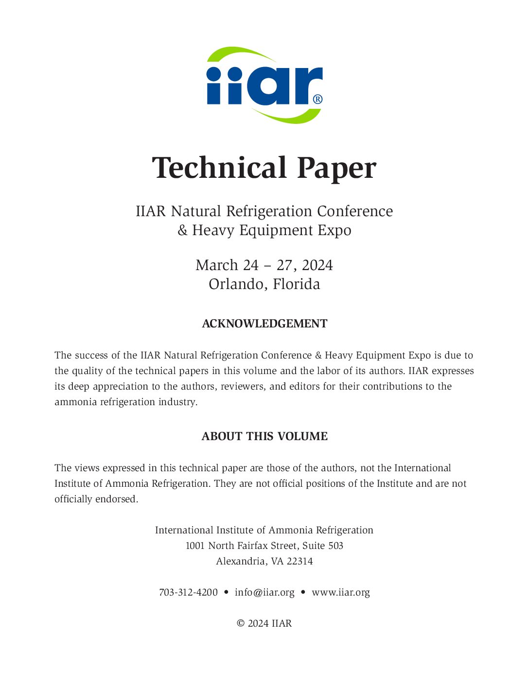
On average, 20% of aging ammonia refrigeration systems contain some level of rogue moisture in the piping insulation, but no systems exhibited moisture in 100% of the piping insulation, as seen in Figure 1. Protective measures to combat rogue moisture in the insulation have been partially effective, considering that these figures continue to decline (down from 30% in 2015). Furthermore, the lowest recorded percentage of water trapped in the ammonia piping insulation evaluated by visual inspection between June 2022 and May 2023 was ~10%, for ~40% of the systems, and the highest percentage of wet insulation was ~55%, for ~5% of the systems.
Where CUI Degrades the Surface of the Pipe
Owing to the numerous factors involved, the progression time from moisture entering the insulation to the point of pipe failure varies widely across systems. Therefore, the rate at which external corrosion thins the pipe wall in an ammonia refrigeration system is not definitive. In particular, the ambient temperature and humidity are not constant or typically controlled. These variables also make it impossible to determine the distribution of corrosion around the circumference of the pipe. Frequently, moisture collects in concentrated areas on the pipe. Moreover, fully soaked insulation often leads to corrosion that forms evenly around the pipe, especially on vertical runs.
These conditions typically occur in thermal cycling areas, such as the section from the defrost condensate tee to the suction line, any other lines that are or will be above freezing, such as hot gas defrost lines, and equipment that is operated periodically. It is common to assume that suction lines are not susceptible because they are constantly operating below freezing. However, it only takes a few days above freezing for the ice to thaw and introduce moisture that begins to corrode the pipe. Furthermore, when these lines refreeze, they swell, and the corrosion and cracking are more destructive.
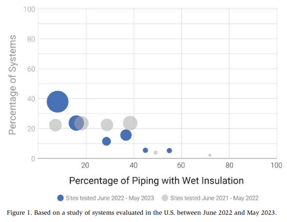
As seen in Figure 2, for example, pipe wall loss can be as high as 71% on lowtemperature suction lines. In aggregate, 81% of systems exhibited pipe wall loss due to CUI on a suction line at the time of testing. Overall, 43% of the evaluated systems were reported to have areas with pipe wall loss of over 50%. The highest recorded loss, not including leaks that occurred as a result of complete metal integrity failure due to corrosion, peaked at 82% wall loss (or 18% remaining wall thickness).
Areas of Susceptibility
By employing practices to prevent and manage degradation, and with regular inspections, it is possible to predict the primary CUI breeding locations and detect where corrosion is present or may soon be present in the system.
Cues that the Piping is Compromised
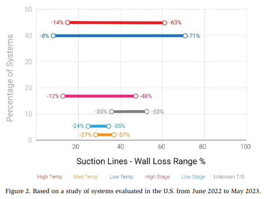
Insulation conditions, such as damaged or missing components of the vapor retarder, can vary. Any damage can allow moisture through the vapor retarder, which is considered irreversible. The following cues should be regularly considered:
- Jacketing separation (see Figure 3)
- Holes in the insulation
- Hail damage
- Split seams
- Crushing from physical damage
- Weld strikes or other electrical damage that penetrate the jacketing
In addition to damage, which is a common catalyst for CUI, the areas where piping is most vulnerable are:
- The intersection of a pipe segment and major pieces of equipment
- Before and after pipe direction changes (e.g., elbows, tees, and reducers)
- Wall and roof penetrations
- Insulation terminations (e.g., valve groups and end caps)
The location of a component or structure can make it challenging to ensure piping integrity. It is necessary to regularly inspect:
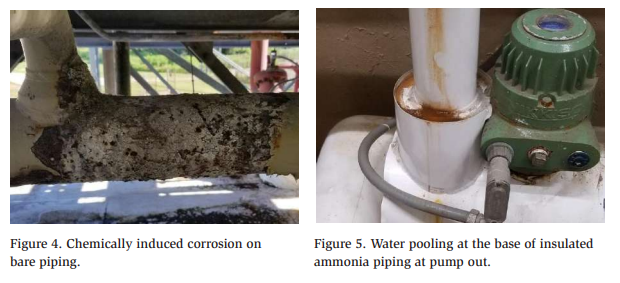
- Piping near condensers or a cooling tower area. This equipment can produce chemical and mineral-rich mists that are especially damaging to pipe jacketing and bare piping (see Figure 4). This mist can leave mineral deposits on metal surfaces, which are prone to corrosion unless cleaned and coated regularly. This is especially detrimental for piping that is not properly protected, like in areas where piping penetrates the walkways, or when the design does not allow for enough room to thoroughly inspect or properly maintain coatings.
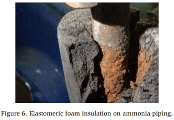
- Gravitational pooling also requires for consideration, specifically related to pump outs and roof penetrations (see Figure 5). Pump outs are commonly installed in the bottom of piping for proper function. However, this positions the piping precisely in the area that collects water after being compromised. Water collects in the lowest area, beneath the piping or in dips of the roof.
- Any area where piping penetrates a boundary, such as a roof or wall, is difficult to inspect and maintain. Additionally, the piping is often uninsulated, leaving the bare piping exposed to moisture. In many systems, these areas are unprotected because they pass through a boundary. Integrity depends entirely on a secure adhesive or sealant, such as caulk, to provide weatherproofing.
- Congested roof drains. Drains that are not regularly cleared can trap moisture and promote the growth of organic materials.
Improper design, poor installation or maintenance, and use of the wrong materials can be equally devastating to piping and other components in ammonia systems. Look for:
- Weak or missing gutters that are not properly channeling rain runoff away from the piping.
- Poor or unmaintained caulking at insulation caps.
- Screws in the jacketing.
- Design configurations that collect or hold water such as insulated hand valves or other vertically oriented features. Although it may look good aesthetically, it may be destructive.
- Be aware of how overlapping jacketing seams may allow water to collect. Seams placed on top of the piping, while quite common, invite water into the system.
- Insulated-to-bare piping transitions at valve groups put stress on the unprotected bare piping, as well as the sealing. If not well maintained, the paint or coating can flake, and visible rust and corrosion soon follow.
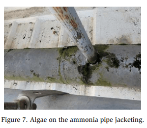
- Fiberglass and elastomeric foam insulation, commonly used for residential air conditioning and plumbing, are prone to waterlogging and should not be used (see Figure 6). Furthermore, elastomeric foam insulation is commonly glued to the surface of the pipe with no outer protection from the elements, which is a of imminent damage.
- Improper pipe supports are hotspots for corrosion and mechanical wear on piping. Thermal piping expansion/contraction in ammonia refrigeration can create wear points on piping if not properly protected from the support itself. The threat is magnified if the bracket design does not allow for proper maintenance and coating of the piping.
- Brackets covered by jacketing. Although it may look nice, it is another area where water is allowed to enter the system. Over time, thermal cycling causes enormous stress on the jacketing, which does not expand but separates at the seams.
Confirmation that the Piping is Compromised
Unfortunately, CUI does not always present itself visually and is commonly hidden. Non-destructive testing (NDT) is recommended to evaluate common areas of failure and locate the wet insulation and corrosion.
Conversely, when the corrosion has advanced, the system shows indications that the piping is compromised. Visible cues reveal that moisture is trapped in the insulation or corrosion is present on insulated piping. Look for:
- Moisture dripping or ice forming around the pipes. This is a sign that the insulation is saturated, exceeding the containment of the jacketing. Ice buildup on insulation typically occurs when water has penetrated the vapor retarder, resulting in ice formations from the surface of the pipe to outside the insulation jacketing, all the way through the saturated insulation.
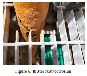
- Biological indicators, such as algae, moss, or plants, growing on the insulation (see Figure 7).
- Rust stains on the insulation jacketing. Rust staining or rust-colored water from within the jacketing occurs as a result of degradation in the piping or components contained inside the jacketing and insulation.
- Rust stains on the floor of engine rooms. Often, this is found near valve groups where the defrosting process produces excessive water exposure.
- Sagging areas on a long run of pipe.
- Painted corrosion. If the surface is not cleaned of all rust before coating, the paint shields the active corrosion and exacerbates the issue.
Building a Framework for Corrosion Intervention
Considering that multiple variables cannot be determined, there is no reliable formula for deriving how much corrosion can occur or how quickly it will advance. Quantitative data reveals that piping exhibiting any of the aforementioned characteristics should be regularly monitored because the formation of CUI and thinning of pipe walls is imminent if not corrected.
Daily system walk-downs and mechanical inspections should be routinely performed to document the suspected areas. Further investigation, maintenance, or replacement of vulnerable or compromised piping in the system should be prioritized based on the level of severity. Because CUI does not always have visual indicators, further testing should be conducted at common areas of failure.
Classifying Severity
The first priority should be given to piping where leaks or fumes are present. Ammonia fumes are usually due to poor packing on the stems of solenoid valves that are actuated; tightening the packing nuts should resolve these leaks.
Where corrosion is present, the remaining pipe wall must be measured to make an accurate assessment of the severity, which is related to the level of priority. Corrosion on bare piping and CUI take on multiple forms and vary in terms of how aggressively they advance. Generally, blister rust is the most concerning form (Figure 8). If the piping shows layers of peeling rust (or blistering), the corrosion is advanced, and the remaining wall thickness is likely not suitable for operation. The general rule of thumb for companies that exercise a conservative approach is to immediately replace piping that exceeds 50% wall loss.
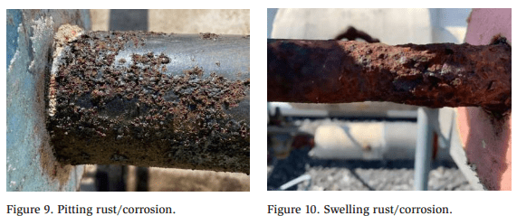
Pitting corrosion is the most common form of corrosion found in refrigeration systems (Figure 9). Pitting is usually a slow process that causes isolated, scattered pits over a localized area. Contrary to blister rust, pitting and swelling rust (Figure 10) both look severe, though oftentimes the piping can remain in service. Where piping has suffered wall loss in the range of 30%–50%, the pipe needs to be cleaned of all corrosion and coated to protect it from moisture.
Areas of wet insulation on piping with low wall loss (less than 30%) should be monitored for advancing corrosion. When replaced, a vapor retarder should be applied directly to the pipe surface, prior to installing the new insulation, to provide a water barrier and protect against infiltration.
Damaged and split jacketing, failed caulking, compromised sealing points, and improperly oriented seams should be addressed promptly. Replace any wet insulation and clean the piping in these areas so that the joints and sealants do not trap existing moisture in the jacketing.
Finally, other vulnerable areas of the system, as a result of proximity or design, should be resolved and inspected regularly to prevent degradation.