


2024 Technical Paper #2
CO2 Systems Add-Ons: Calculations and Field Measurements
Author: Giacomo Pisano, CO2 Business Development Manager, and Nabih Hussein, Refrigeration Sales Engineer DORIN USA
Abstract
This paper describes enhanced and integrated carbon dioxide refrigeration systems that can improve yearly energy figures when compared to traditional flash-gas bypass (FGB) solutions, making CO2 an attractive option for industrial refrigeration in some regions.
The typical FGB solution represents the simplest transcritical carbon dioxide (CO2) system configuration, but it suffers energy efficiency penalties with higher heat-sink temperatures, leading to unfavorable yearly energy efficiencies at warmer latitudes.
This paper provides a detailed description of various CO2 systems. Starting from FGB configuration, in-depth energy efficiency analysis is provided, including job site field experience. Then, several FGB add-ons are described, including parallel compression; liquid and vapor ejectors; adiabatic cooling; and line start permanent magnet electric motors. Each add-on contribution is analyzed with calculations and field measurements.
We also describe CO2 system integration, showing how heat recovery and air-conditioning can be integrated into the same refrigeration unit, thus making any specific building completely self-sufficient from an energy standpoint. The same CO2 system is able to perform both low- temperature and medium-temperature duties, together with providing sanitary hot water, comfort cooling during summer, and heating during winter. Again, this integration is analyzed from a theoretical standpoint, and then concrete examples with field measurements are shown.
Introduction
Threats of ozone depletion and global warming have accelerated the use of carbon dioxide (CO2) as a refrigerant in the last two decades, leading to development of the flash-gas bypass (FGB) configuration, the most cost-effective execution for a CO2 transcritical system.
Heat sink temperature plays a key role for this system’s performance. In the case of an air-cooled cycle, when ambient temperature exceeds 73°F, no condensation can occur and the high-pressure heat exchanger will not condense the CO2 stream, the reason for it being called “gas cooler.” The heat-sink temperature determines the gas cooler’s high pressure, which optimizes the system coefficient of performance (COP), as shown in Figure 1
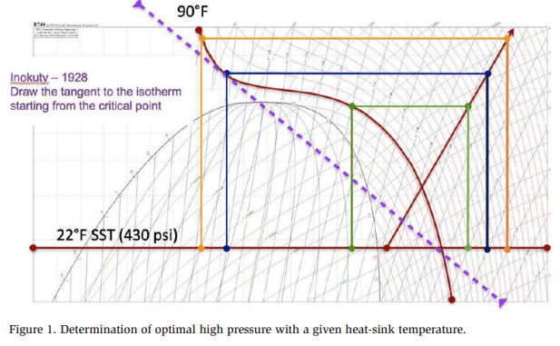
Figure 1 shows an air-cooled compression process starting from 430 psi (corresponding to 22°F SST) with an ambient temperature of 90°F and assumes an infinite gas cooler surface equalizing gas cooler outlet and heat-sink temperatures. With no condensation, infinite head pressures fulfil the gas cooler outlet temperature constraint, and one may choose to end compressing anywhere above the critical pressure. This results in significant performance differences with varying discharge pressures. Figure 1 also shows that there is a specific end-of-compression pressure optimizing the cycle COP, presented graphically by drawing the tangent line starting from the critical point (87°F at 1045 psig) to the gas cooler outlet isotherm [1].
This optimal head pressure varies with heat-sink temperature: a lower higher-heatsink temperature will lead to a higher optimal pressure, as shown in Figure 2.
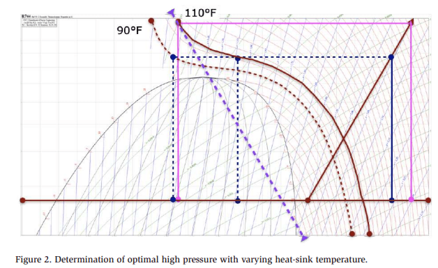
Figure 2 also shows that a severe deterioration in performance takes place with increasing heat-sink temperatures, with COP(90 °F) > COP(110 °F) where:
COP(90 °F) is the system COP with 90°F ambient temperature.
COP(110 °F) is the system COP with 110°F ambient temperature.
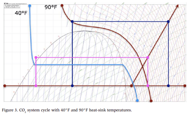
At the same time, a decrease in heat-sink temperature leads to a COP improvement, especially when it comes to subcritical system operation which will typically be in place for ambient temperatures below 73 °F. Figure 3 shows a subcritical CO2 cycle which could be representative of a mild day with 40°F ambient temperature and demonstrates a tremendous COP improvement, with COP(40 °F) >> COP(90 °F). Calculations show that a 4% increase in COP can be gained for each 2°F in ambient temperature reduction during transcritical operation. When subcritical operation is in place, COP improvement is even more consistent. For instance, going from 90°F ambient to 40°F leads to a 300% COP improvement.
At the same time, a decrease in heat-sink temperature leads to a COP improvement, especially when it comes to subcritical system operation which will typically be in place for ambient temperatures below 73 °F. Figure 3 shows a subcritical CO2 cycle which could be representative of a mild day with 40°F ambient temperature and demonstrates a tremendous COP improvement, with COP(40 °F) >> COP(90 °F). Calculations show that a 4% increase in COP can be gained for each 2°F in ambient temperature reduction during transcritical operation. When subcritical operation is in place, COP improvement is even more consistent. For instance, going from 90°F ambient to 40°F leads to a 300% COP improvement.
It is also interesting to note how CO2 allows operation with much lower condensing temperatures when compared to standard hydrofluorocarbon (HFC) cycles: in fact, the higher operating pressures always provide enough pressure differential for the metering device to function correctly, permitting condensing temperatures as low as 40°F, when a consistent gas cooler design is in place.
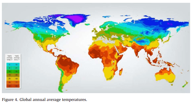
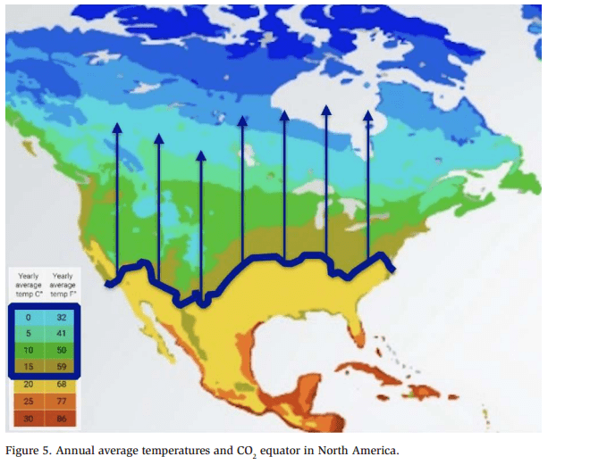
Considering these arguments, it is clear how standard FGB CO2 systems can offer great yearly efficiency levels in cold-to-mild environments, while efficiency penalties must be accounted for in warmer environments. For this reason, over the course of the last decade, an efficiency-restricted “CO2 Equator” has been defined in literature, showing the territorial limitation for efficient FGB CO2 system execution when compared to other refrigerants, depending on average ambient temperature (Figure 4). These limitations see annual energy consumption of a CO2 system larger than an equivalent HFC system for average ambient temperatures above 59°F (15°C) [2]. Therefore, in North American jurisdictions, a standard CO2 FGB cycle is only an efficient solution above the blue line depicted in Figure 5.
CO2 System Add-ons
During the last decade, numerous CO2 system add-ons have been successfully introduced in order to improve CO2 system efficiency in warmer environments (i.e., below the aforementioned blue line). This paper will address the following add-ons: parallel compression, vapor and liquid ejectors, adiabatic cooling, and compressors with permanent magnet electric motors.
Parallel Compression
A simple FGB system can be modified by implementing parallel compression. In a typical flash-gas bypass system, the flash gas building up in the intermediate pressure receiver is diverted toward the compressors suction, as shown in Figure 6.
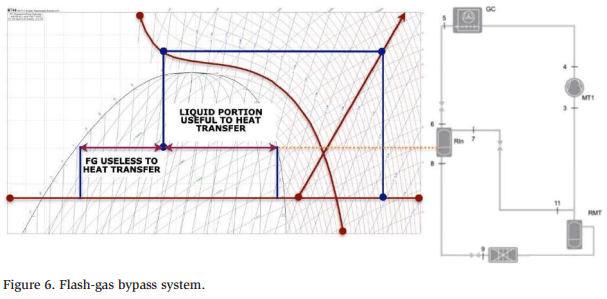
This bypass is in place because flash gas is not useful to heat exchange in the evaporators and it is therefore not efficient to circulate this back and forth from and to the evaporators, especially in the case of large distributed systems.
Instead of bypassing intermediate receiver flash gas, parallel compression is a kind of execution where an additional set of compressors is in place, sucking gas directly from the intermediate pressure receiver, as shown in Figure 7.
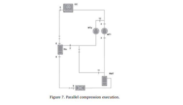
During warmer seasons, a significant portion of the total CO2 mass flow exiting the high-pressure valve consists of flash gas, building up pressure in the intermediate pressure receiver, accounting for as much as 45% of the total mass flow leaving the high-pressure valve. By using parallel compression, this large amount of refrigerant mass can be compressed from the intermediate receiver pressure to the gas cooler pressure, instead to the evaporator pressure, leading to a COP improvement in the range of 7% at peak temperature [3].
Liquid ejectors and vapor ejectors.
Ejectors are a means to further improve CO2 system efficiency. They convert highpressure potential energy in the motive flow (gas cooler outlet refrigerant stream)into kinetic energy, drawing a flow from a suction port (evaporator outlet refrigerant stream). Two main kinds of ejectors are normally considered: liquid ejectors and vapor ejectors.
Liquid Ejectors
In typical direct expansion (DX) systems, a consistent part of the evaporator line is used in order to assure enough superheat and avoid liquid refrigerant returning to the compressors suction line. This leads to safe compressor operation but introduces efficiency losses since the super-heating phase into the evaporator coil will feature a very limited heat transfer.
The use of liquid ejectors allows the system to work with ideally no superheat at the evaporator outlet, thus maximizing the heat transfer. The evaporator’s outlet is wet and streams into a generously sized low-pressure receiver (LPR), where the liquid excess accumulates at the bottom, to be sucked by the liquid ejector and compressed into the intermediate pressure receiver. This process lifts the saturated evaporating pressure/temperature up to 9R, greatly improving system efficiency.
Vapor Ejectors
The flash gas amount accumulating at the bottom of the low-pressure receiver can also be compressed by means of the vapor ejector into the intermediate pressure receiver. This will lead to a significant increase in the mass flow available for parallel compression, bringing further efficiency improvement. It also creates a need for multiple parallel compressors to cope with variable load conditions. It is not necessary for liquid and vapor ejectors to be implemented at the same time; however, the inclusion of a liquid ejector will increase vapor-ejector effectiveness. The vaporejector entrainment ratio (the amount of fluid the ejector is able to suck at given boundary conditions) will increase with decreasing pressure differences; if a liquid ejector is not in place, the vapor ejector will work with a larger pressure difference due to the evaporation pressure lift introduced by the liquid ejector itself.
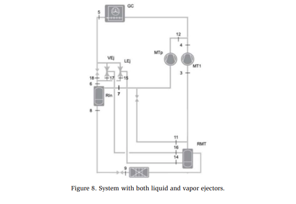
The implementation of both liquid and vapor ejectors leads to further COP improvements in the range of 16% at peak ambient temperatures [3]. Figure 8 shows a system layout featuring both liquid and vapor ejectors.
Adiabatic
Cooling An adiabatic gas cooler is made of water-wetted pads located outside the condenser coils; this helps to decrease the CO2 gas cooler exhaust temperature and therefore delays transcritical operation of a booster system. A water valve is triggered when the ambient temperature exceeds 70°F. Water is sprayed on the pads, the gas cooler fans pull air through the wet pads, and the air becomes humid and cooler prior to passing through the coils. This significantly helps in making the system up to 16% more energy-efficient, depending on the specific job site location and ambient temperature profile.
Permanent Magnet Motors
Typical permanent magnets motors (PMM) are designed with magnets embedded into the motor rotor, in most cases their stators feature the typical squirrel cage design, very similar to that of a standard asynchronous motor.
PMMs are synchronous, this meaning there is no slippage between rotor and stator magnetic field, leading to much lower electric losses.
Typical PMMs need an external drive (inverter); however, a new technology—line start permanent magnets (LSPM)—is now available from various electric motor suppliers. LSPM electric motors are a hybrid configuration between the standard asynchronous design and the permanent magnets technology, as shown in Figure 9.
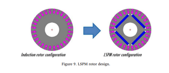
With this design it is possible to energize the electric motor directly online, with no need for an inverter. The motor will start as a standard induction motor and switch to synchronous operation within milliseconds. Besides the cost effectiveness (because there is no need for an external inverter), this electric motor configuration allows the ability to achieve a very interesting efficiency improvement. Lab tests have demonstrated that compressor energy efficiency ratio (EER) improvements are above 12%, depending on the operating conditions, as will be shown in a later section.
Calculated Performance Improvements for CO2 System Add-ons
The various CO2 system add-ons bring consistent efficiency improvements, which are documented by means of a specific software [4], capable of simulating various system designs, including flash-gas bypass, parallel compression, liquid and vapor ejectors, adiabatic cooling, and permanent magnet motors. Calculations have been made assuming the following system specifications:
- LT load: 3.000 kbtu/h @ -22°F SST
- MT load: 6.000 kbtu/h @ +22°F SST
- Max ambient temperature: 95°F
Calculations with a simple flash-gas bypass execution suggest a peak temperature EER of 5.89. The same system designed with parallel compression execution, brings EER to 6.30. Implementing both liquid and vapor ejectors further improves the EER to 6.93. When adiabatic cooling is also considered, then EER is brought up to 8.03. If permanent magnet motors are used for the medium-temperature suction group and for the parallel compression group, then EER reaches the remarkable level of 8.75. Figure 10 shows the various system configurations and the specific software output.
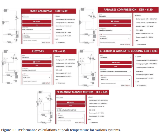
Theoretical calculations show that the aforementioned CO2 systems add-ons are confirmed to bring significant energy efficiency improvements; keeping the simple flash-gas bypass execution as the baseline, calculations show that following improvements are achieved:
- Parallel compression: +7%
- Ejectors: +11%
- Adiabatic cooling: +16%
- Permanent magnet motors: +9%
Since these results are derived through mathematical system modelling, it may be argued they do not really represent field figures. The following section shows real-world examples where field measurements were noted for several different CO2 systems.
Field Measurements for CO2 System
Add-ons Any refrigeration system in real-world operation is subject to boundary conditions, which impact its efficiency. It is therefore difficult to calculate rigorously the individual influence of any one of the CO2 systems add-ons previously described. Nevertheless, some of these have been documented and recorded.
Adiabatic Cooling
A CSF supermarket in Beijing, China [5], has been equipped with a CO2 transcritical refrigeration system. Especially during summer, the local weather is very dry, which led engineers to choose an adiabatic gas cooler design. However, due to a minor issue, the adiabatic gas cooler water pads were not put in operation during the first days of the system operation, which was in July. Water pads were applied shortly after this installation, with notable energy efficiency benefits.
During these days the main system operating parameters were monitored, with a special focus on the gas cooler operation, with measurements shown in Figure 11.
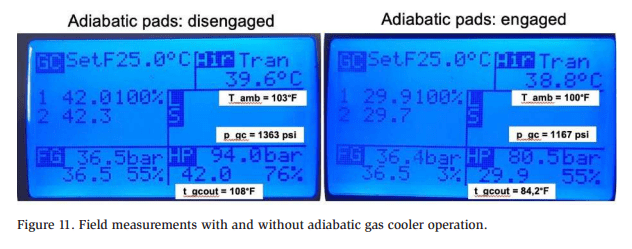
During operation without water pads, and with an ambient temperature of 103°F, gas cooler operating pressure was set to 1363 psi with a 76% HP valve closing and a gas cooler outlet temperature of 108°F.
When water pads were added to the system, with a very similar ambient temperature of 100°F, it was possible to significantly decrease gas cooler pressure to 1167 psi, obtaining a gas cooler outlet temperature of 84.2°F: this shows how beneficial the use of an adiabatic gas cooler is from an efficiency perspective, especially in very dry areas, and confirms the prospected 16% EER improvements mentioned in the previous section.
Liquid Ejectors
A Migros supermarket in Bulle, Switzerland [6], was one of the first sites where ejector technology was deployed. At the time, some of the vending area evaporators had been equipped with instrumented coils; the given cabinets were meant to keep air outlet temperature at 31°F and thermocouples were attached to various coils bends, so to monitor fluid temperature during system operation. The system was made to run with and without liquid ejectors, with results being shown in Figure 12.
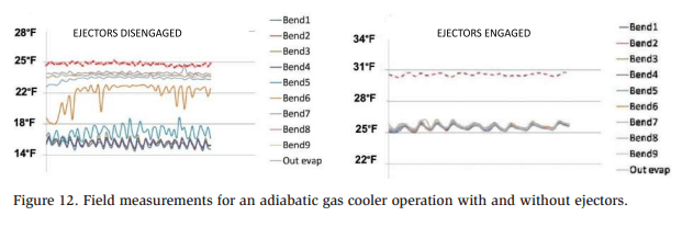
Figure 12 shows evaporator bends temperature profile with ejectors being
Figure 12 shows evaporator bends temperature profile with ejectors being disengaged (left) and engaged (right). When ejectors are not in operation, the bends temperatures are maldistributed between 14°F and 25°F (16°F as the mean mass weighted value), this being explained by a certain degree of superheating inside the coils. Superheating is typically necessary to avoid liquid return to compressors but adversely affects coil heat transfer due to poor sensible heat rejection. When ejectors are engaged, bends temperatures are evenly distributed and collapse to an average of 26°F: no sensible heat is in place and refrigerant latent heat can be fully exploited within the coils, leading to a consistent increase in average evaporation temperature and a strong reduction in the coil delta T. In this way, system efficiency is strongly improved, and the 11% COP improvement mentioned in the previous section is therefore confirmed.
Permanent Magnet Motors
To evaluate compressors’ performance improvements arising from the use of permanent magnet motors, a CO2 transcritical test rig has been used. Its basic piping and instrumentation (P&I diagram) is shown in Figure 13.
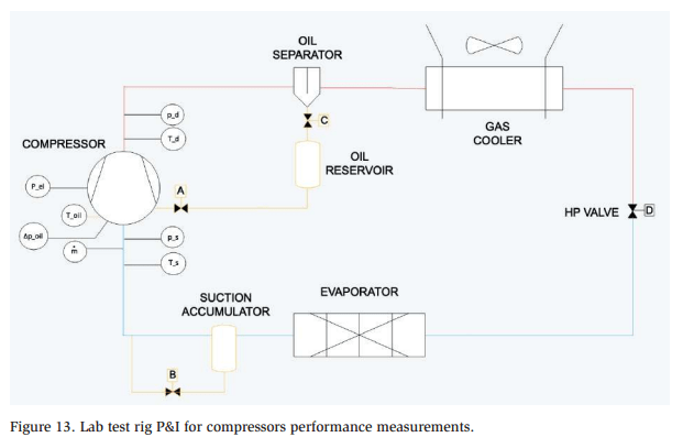
The following measurements were performed:
- p_S: suction pressure
- T_S: suction temperature
- m: refrigerant mass flow
- P_el: power consumption
- p_D: discharge pressure
- T_S: discharge temperature
Two different compressors executions were tested: compressor A was a 50 hp CO2 transcritical model, while compressor B was identical to compressor A with the exception of the sole rotor, which was equipped with permanent magnets. This kind of test is representative of the real permanent magnet’s benefits, as no difference is in place between compressor A and compressor B from a mechanical standpoint (both have the same components and the same tolerances), the only difference is the rotor execution, one with and one without permanent magnets.
A comprehensive test campaign was performed with the compressors’ performance being compared at different operating conditions, as shown in Figure 14.
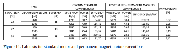
Figure 14 shows that compressor B execution with permanent magnet motor significantly outperforms the standard execution and confirms the 9% performance improvement indicated in the previous section.
Conclusions
Carbon dioxide is an environmentally friendly alternative to synthetic refrigerants and offers very good performance levels in many applications. However, the typical flashgas bypass execution suffers from an efficiency penalty with increasing heat-sink temperatures, limiting its widespread use in all climates. However, during the last decade, several add-ons to such systems have been shown to perform well, from both from a calculation and experimental standpoint:
- Parallel compression
- Liquid and vapor ejectors
- Adiabatic cooling
- Permanent magnet motors
Depending on the given system boundary conditions (e.g., jobsite location, local humidity, refrigeration load profile, etc.) it may make sense to implement all of them, which may bring the system to a COP improvement above 40% when considering the flash gas bypass execution as the baseline.
References
[1] M. S. Bhatti. 1997. “A critical look at R-744 and R-134a Mobile Air Conditioning Systems.” Journal of Passengers Cars, Part 1, pp 181-205.[2] K. Visser. 2018. “Moving the CO2 ‘equator’ from the northern Mediterranean to Malaysia without ejectors.” Proceedings of IIR 2018 – International Institute of Refrigeration – paper 0018.
[3] K. Madsen. 2018. “Financial aspects of ejector solutions in supermarkets and smaller industrial systems.” Proceedings of IIR 2018 – International Institute of Refrigeration – paper 0010.
[4] DORIN selection software, online version, Release 23.11, “selection.dorin.com.”
[5] L. Rossi, 2018: Atmosphere China, “Architecture Sustainability – From Switzerland to Beijing, CO2 refrigeration in a local supermarket.”
[6] Frigoconsulting, 2013, Migros supermearket in Bulle, First ejector operating successfully, “https://frigoconsulting.ch/en/casestudy/migros-bulle/.”