The Design of CO2 Refrigeration System Using Ammonia System Design Principles
K. VISSER, HON.M.IIR , FINSTR, M . IIAR, M.ARA, M.KNVVK, M.EURAMON
PRINCIPAL, KAV CONSULTING PTY LTD
ABSTRACT
Over the past 20 years or so the use of CO2 refrigerant as the first stage of CO2/HFC and CO2/NH3 cascade systems has increased significantly. The use of two-stage transcritical CO2 systems, which are invariably air cooled, is an increasing trend. Frequently, two-stage gas coolers are used with water sprayed on the second stage air-cooled gas coolers to reduce the gas cooler exit temperature to as low a value as possible.
The latest trend is using ejectors to partially recompress the flash gas with the transcritical gas cooler exit fluid in an effort to improve the very poor coefficients of performance (COPs) resulting from gas cooler exit temperatures significantly higher than the CO2 critical temperature of 31.1°C (88°F). COP improvements of 10–30% have been reported when using ejectors.
This paper demonstrates that the application of evaporative condensers, which are commonly used in ammonia refrigerating systems, to condense subcritical CO2 and gas cool transcritical CO2 fluid will permit the efficient application of CO2 refrigeration worldwide if ammonia design principles are followed.
By using the ambient wet bulb design temperature (AWBDT) as the condensing and gas cooling base temperature instead of the ambient dry bulb temperature, all CO2 refrigeration applications are brought within the scope of efficient applications worldwide. CO2 refrigeration that employs evaporative condensers and gas coolers, if used with parallel compression, will be at least as efficient, if not more efficient, than ammonia refrigerating systems.
Once the CO2 refrigerant is in a subcritical condition it behaves much like ammonia, and hence ammonia refrigerating system design principles become appropriate. However, thermophysical properties of CO2 require adjustment in the values of separation velocities in accumulators and suction traps and values are recommended in the paper. Similarly, several tables in the paper show the capacities of dry suction and wet return lines and liquid lines capacities.
Oil separation techniques and automatic oil return methods in both CO2 direct expansion (DX) and liquid recirculation systems are explained and design guidelines are provided.
INTRODUCTION
The author acknowledges his late dear friend Prof. Dr. Gustav Lorentzen for reviving his interest in CO2 refrigeration in the mid-1980s when the ozone depletion potential of CFCs and HCFCs became evident (see Figure 1). This resulted in the Montreal Protocol (MP) to phase out the use of CFCs and HCFCs and to prohibit their production and use after certain dates. We celebrate Gustav Lorentzen’s 1993 public call for the revival of the use of CO2 every two years with the IIR Gustav Lorentzen Natural Refrigerants Conference (IIRGLNRC). The first of these was held in Hanover, Germany, in May 1994. The 12th IIRGLNRC was conducted in Edinburgh, Scotland, in August 2016.
The eminent refrigeration scientist Dr. S. Forbes Pearson designed the first application of CO2 in the modern era in 1992. The system comprised two flooded CO2 evaporators in which the CO2 vapor is condensed in an ammonia-cooled plate heat exchanger. A demonstration unit was installed in a small -23°C cold store at Marks and Spencer p.l.c., Kilmarnock, Scotland. CO2 hot gas for defrost was generated in a CO2 boiler heated by ammonia from the discharge of the ammonia compressor (Pearson 1992).
The term revival of CO2 is correct. As Professor Risto Ciconkov of The Saints Cyril and Methodius University of Skopje in Macedonia shows so eloquently in Figure 2 (private communication), CO2 and ammonia were commonly used in all manner of cooling and freezing applications from the 1870s to the 1940s, including cooling for human comfort, e.g., the cooling in some cinemas in Sydney until about 1966. But after the advent of CFCs (R12, etc.) in the 1930s, the use of CO2 rapidly declined.
Luckily ammonia (NH3) survived as a natural refrigerant for industrial applications.
BACKGROUND
The author has personal experience with CO2 refrigeration on board a ship, which took frozen meat east from Buenos Aires, Argentina, to Yokohama, Japan. A CO2 plant provided refrigeration. Gustav Lorentzen described a similar experience as a young man before World War II sailing between Norway and China. The author’s main CO2 design experience was gained with the design of a multifunction two-stage transcritical CO2 refrigerating system with parallel compression (MF2STCCO2RSPC). In September 2009, Exquisine Pty. Ltd. decided to install a two-stage transcritical CO2 refrigeration plant to replace 22 independent systems providing heating and cooling at its Thornbury, Victoria, food-processing facility where high-end frozen dairy desserts are manufactured. The system was supported by a 50% grant from Aus Industry, an Australian federal government department, under the Re-Tooling for Climate Change program. A CO2/ammonia cascade plant was briefly considered, but with residential properties bordering the site, it was judged best not to use ammonia. Plant noise was also a potential problem (Visser 2012).
The new two-stage transcritical CO2 refrigeration plant carries out all the required blast freezing, cold and chilled product and ingredient storage, factory and packing area cooling, and chilled process water cooling. In addition the system heats all potable tap water for sanitary and factory cleaning purposes. Process hot water is also partially generated to provide A/C reheat and space heating for the office and factory. A secondary ethylene glycol circuit provides underfloor and door jamb heating for two large cold store and three blast freezer doors and highly effective freezer evaporator defrost.
The 22 existing systems being replaced by the new system comprise four individual systems for blast freezing and cold storage—one of each—and two chillers. In addition are one independent chilled water system, one evaporative cooler used for factory cooling, four reverse cycle office A/C units, six air-to-water heat pumps, three gas-fired mains pressure hot water systems, and four electric underfloor and freezer door circuits. One of the most critical parts of the design was the oil management. To that end the six transcritical compressors were each equipped with an oil separator, while the three boosters share one unit. The specific savings per unit production amount to a 33% reduction in electrical energy consumption, a 60% reduction in natural gas consumption, a 44% reduction in direct and indirect global warming emissions, and a 40% reduction in cooling water consumption (Visser 2012).
This 2010 full-scale prototype plant employed a two-stage gas cooler with water spray on the second stage. Observations of the somewhat erratic operation led to the idea that an evaporative condenser (EC) would greatly improve the situation (Ball and Visser 2015; Visser 2014a, b, d, 2015a). Hence the second MF2STCCO2RSPC now under construction for a cook/freeze facility for the NSW Department of Corrective Services near Sydney incorporates an evaporative condenser.
ADVANTAGES AND DISADVANTAGES OF R744 (CO2)
The advantages and disadvantages of CO2 as a refrigerant are summarized below.
Advantages
Advantages of R744 include the following:
High volumetric performance
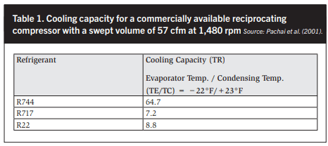
In the range of −55°C (−67°F) to 0°C (32°F) evaporating temperatures, the volumetric performance of CO2 is 4–12 times better than that of NH3. This means that CO2 compressors and suction piping systems are smaller than for equivalent capacity NH3 systems. See Figures 3 and 4 and Table 1.

Low compression pressure ratio
In the case of CO2, the compression ratio is about 20 to 50% lower when compared with HFCs and ammonia. See Figures 3 and 5 and Table 2.
The lower compression ratio combined with the higher-pressure levels give greater volumetric and isentropic efficiencies. Stoecker (2000) quantified the beneficial impact of the combination of low compression ratios and higher pressure on both the volumetric and isentropic efficiencies. See Figures 6 and 7.
The overall benefit of low compression ratios is that the real relative COP (immediate COP) is 15 to 20% higher than the theoretical relative COP in the case of CO2. See Figure 3d.
High heat transfer during evaporation
Figure 8 presents a very interesting comparison and variation of the overall heat transfer coefficient of CO2 and R22 with logarithmic mean temperature difference (LMTD). A most outstanding feature of CO2 is the almost constant U-factor for CO2 with LMTDs ranging from 3 to 18°F.
In practice, this means that CO2 evaporators may be made significantly smaller and low air-to-refrigerant approaches are possible in heavy-duty low temperature freezing applications. Increasing the mass velocity in the refrigerant circuits also enhances evaporator performance. This is possible as evaporator circuit pressure drops 7–10 times higher for the same drop in saturation temperature are allowable in CO2 evaporators. This means fewer evaporator circuits with higher circuit loading at relatively low recirculation rates compared with NH3 (say n = 1.5 for CO2 instead of n = 4 for NH3). See Figure 9 for saturation temperature drop with respect to pressure drop.
Considering Figure 10, clearly CO2 used as a one-phase liquid brine is superior in every respect compared with other brines in terms of temperature difference—heat transfer—and pressure loss factors.
CO2 may also be used as a volatile brine as demonstrated by Pearson in 1992. CO2 may be used in direct systems in the spaces to be cooled, which would give the highest possible evaporating temperature at the highest efficiency.
Inert gas
CO2 is an inert gas, and hence the choice of metallic materials for piping and components generally does not present a problem provided dry CO2 is used and the system components can handle the maximum design pressures. Attention must be paid to the compatibility of elastomers in contact with CO2 (gaskets, o-rings, etc.).
Environmental implications
With respect to global warming potential (GWP), the effect of CO2 refrigerant escaping into the atmosphere is neutral as CO2 is already present in the air. Although CO2 is a greenhouse gas, its use as a refrigerant will be completely neutral because CO2 is a byproduct of existing processes (internal combustion engines, thermal power generation) or as part of an ecological cycle. Allowing the GWP of CO2 is one, it can be argued that CO2 sequestered in a refrigeration system has a GWP of zero.
Occupational health and safety
In Australia, the threshold limit value (TLV) is 5,000 ppm with a short-term exposure limit (STEL) of 30,000 ppm. These numbers were set in 1990. The TLV of 5,000 ppm is almost universally accepted with STEL levels varying between 10,000 to 30,000 ppm with time limits imposed on the duration of exposure.
CO2 cannot burn or explode. Also, at very high temperatures, such as during a fire, CO2 does not create hazardous gases, such as phosgene and hydrofluoric acid, which are created at high temperatures with CFCs and HCFCs, and hydrofluoric acid and carbonyl fluoride, which occur when incinerating HFC at high temperatures.
Figure 11 clearly shows that in the case of evaporators with identical circuit pressure drops, CO2 is superior to both HFCs and ammonia.
Existing CO2 production facilities
Compared with the present production and consumption of CO2, the consumption of CO2 by refrigeration plants in future will be very small indeed.
Low cost and lower required volume
CO2 is quite cheap when bought in industrial quantities. The pure CO2 required for refrigeration will not cost more than ammonia and will cost a fraction of the high cost of modern HFCs and a small fraction of the new HFO refrigerants that are now promoted to replace high GWP HFC under the auspices of the MP. The highly poisonous combustion gases from burning HFOs raise serious concerns. This has led three leading members of the German Motor Vehicle Association—Mercedes Benz, BMW, and the Volkswagon Group—to opt for CO2 refrigeration mobile air condition (MAC) applications.
Because of smaller pipes, evaporators, and compressors, a smaller volume charge of CO2 may be required compared with an ammonia system of equivalent capacity. However, note that the density of liquid CO2 compared with liquid NH3 is about 1.5 times higher. This means that for large industrial systems with most of the liquid refrigerant in pump recirculators and pump-feed evaporators (large plate freezers, large air coolers, etc.), the mass charge of CO2 will be usually larger than for a comparable NH3 system— even if the volumetric charge should be somewhat smaller.

High operating pressure
The high operating pressure is an advantage as it permits the compressor discharge pressures to reduce to low levels with diurnal and seasonal variations in ambient dry and wet bulb conditions. This produces high average COPs resulting in CO2 plants being more efficient than all other refrigerating plants using ammonia, hydrocarbons, HCFCs, HFCs, or HFOs.
Easy to service
CO2 may be blown off when servicing refrigeration system components, as it is harmless and cheap. However, special procedures are required to ensure that no dry ice is formed in a system when it needs to be opened up.
Disadvantages of CO2
The temperature ranges from the triple point at −56.6°C (−69.9°F) and the critical temperature of +31°C (87.8°F), which limits the application in conventional air- cooled refrigeration cycles. See Figure 12.
High design pressure
When air-cooled CO2 systems are built, they need to be designed for up to 120 bar maximum working pressure (MWP) for transcritical operations in an effort to maximize energy efficiency, which is generally very poor even with band-aids like ejectors (see Table 3 and Figure 13). Existing high-pressure compressed natural gas (CNG) compressors suitable for pressures up to 350 bar and crank case pressure up to 70 bar are very likely suitable to be modified for high-pressure CO2 operations with appropriate piston, cylinder, and valve configurations for high mass flows. The high pressures do not cause a major increase in risk, as the risk is determined by the energy content of the system, i.e., the pressure times the volume (p x V). In CO2 systems the volume is very small compared with conventional refrigeration systems and thus the higher pressures do not result in an increase in potential energy if a sudden rupture occurs.
Special precautions, equipment, or procedures for long shutdown periods of CO2 plants
CO2 plants for low-temperature operation with design pressures up to 52 bar require special consideration as follows:
- Use a small, independent CO2- condensing unit to re-condense CO2 vapor and expand the CO2 back into the system. Ensure that an independent power supply, such as a diesel-driven generator to start the system automatically when required, is included.
- Control pressure by means of CO2 vapor re-condensing using a small independent HFC or ammonia refrigeration unit with a diesel engine driven compressor or generator.
- Locate the low-pressure receiver and/ or intercooler in a refrigerated warehouse at temperature of 0°C (32°F) to −30°C (−22°F). Alternative methods are fade-out vessels or controlled blow off.
High density of CO2 vapor
Like CFCs, HCFCs, and HFCs, CO2 is denser than air and tends to displace the atmosphere. In confined spaces (basements, ship holds) CO2 could reach high concentrations. Any person entering such a space would risk health damage. In practice, this is considered to be a manageable risk with proper leak detection and space ventilation in place.
Furthermore, CO2 is odorless and as such will not be noticed by people when entering a space containing a high concentration of CO2. Thus, reliable portable CO2 detectors are required to ensure personnel safety in confined spaces. Short-term exposure levels to CO2 concentrations above 60,000 ppm (6%) are still tolerable but can be fatal if exposure is too long.
EXAMINATION OF ENERGY EFFICIENCY OF CO2 REFRIGERATION SYSTEMS
The COPs of semiautomatic CO2 compressors are based on motor input, while open ammonia compressor COPs are based on power input into the compressor shaft, i.e., BkW or brake horsepower. When comparing these COPs, semihermetic CO2 compressors are at a disadvantage. An electric motor efficiency of 90% has been assumed for the electric motors driving the semihermetic compressors to arrive at estimated values for raw COPs based on compressor shaft power input. This allows COPs of semihermetic and open compressors to be compared on an equal basis.

The excellent heat transfer properties of CO2 allow CO2 condensing at 30°C (86°F) saturated condensing temperature (SCT) at an ambient wet bulb design temperature (AWBDTs) of 24°C (75.2°F) to 25°C (77°F). Gas cooler exit temperatures of 30 to 31°C (86 to 87.8°F) are achievable with AWBDTs of 28°C (82.4°F). An AWBDT of 28°C (82.4°F) is not exceeded in 98% of the world’s climates.
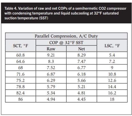
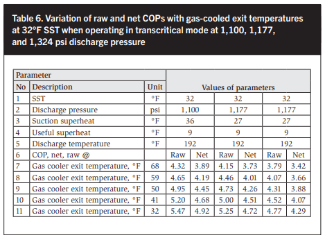
In the following sections all CO2 compressor capacities and energy consumption values used are from one manufacturer, which only manufactures semihermetic compressors. In Tables 4 and 5 and Figures 14 and 15 the net COP is based on the electric motor input while the raw COP is based on a 90% electric motor efficiency. An isentropic efficiency of 75% has been assumed and closely matches derived values. The raw COPs listed in Tables 6 and 7 are shown graphically in Figures 16 and 17.
Clearly the gas cooler exit temperature has a major impact. Therefore cooling transcritical CO2 fluid with a coolant temperature close to or above the critical point of CO2, 88°F, is thermodynamic nonsense. The industry understands this well as COPs are very low. In an effort to improve the COPs of ambient air-cooled transcritical CO2 systems, ejectors are increasingly used to compress some of the flash gas vapor from the first expansion stage and, increasingly, in additional applications. The entry cooling air approach at the gas cooler CO2 exit is 9°F in an air-cooled transcritical CO2 refrigeration cycle. Minetto et al (2015) and Kriezi et al (2015) have reported COP improvements of 6 to 25%. In Table 7 the net and raw COPs are plotted at six discharge pressures from 1,100 to 1,765 psi, which include a 25% increase on COP due to (an) ejector(s) being used. Figure 17 plots the six sets of COP values.
Clearly the COPs in Figure 17 compare very unfavorably with COPs in Figures 13–16, which are based on evaporative condensers/gas coolers (EC/ GCs). This is to be expected because in EC/GCs the ambient wet bulb temperature becomes the initial coolant temperature rather than the ambient air dry bulb temperature, which is the coolant temperature in air-cooled systems. Manufacturers of air-cooled gas coolers realize that air-cooled gas coolers have limitations and offer their products with water sprays on the gas cooler coil face that are activated during hot weather. It is only a small step from this wasteful use of water to full evaporative condensing. Pearson comes to a similar conclusion (2010).
DESCRIPTION OF A CO2 REFRIGERATING SYSTEM FOR A MEAT PACKING PLANT AND ESTIMATED LOADS
A medium size meat packing plant for beef has been chosen as a working example.
Plant production definition
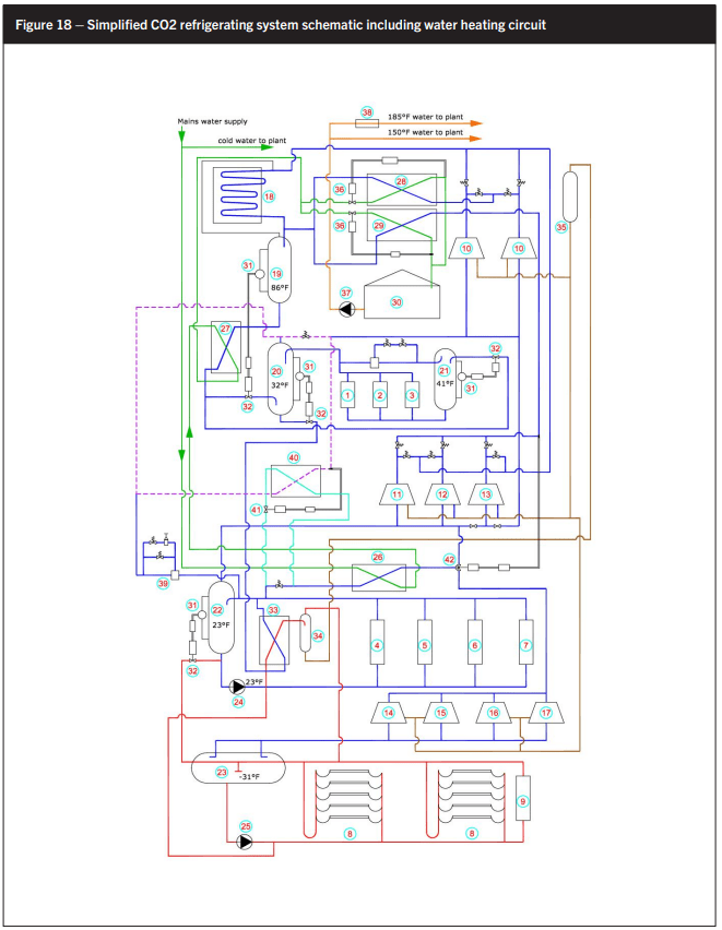
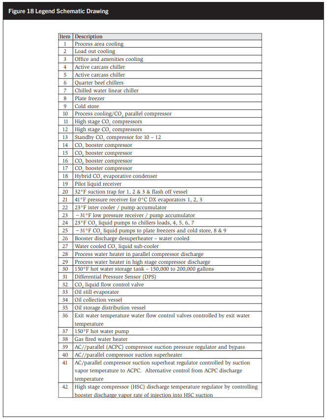
At this plant 1,000 head of bovine livestock are converted into beef with an average dressed weight of 770 lb/head. Thus the total daily carcass weight production is 770,000 lb. The carcasses are chilled in hot boxes before entering the fabrication rooms (FR) for deboning, yielding about 70% producing about 540,000 lb of red meat. Seventy percent of this, i.e. 378,000 lb, is frozen with 72,000 lb of edible offal like hearts, livers, kidneys, etc. Process areas like the Fabrication Room, offal packing room, load out, and office and welfare areas need cooling as well. See Figure 18.

Refrigeration loads
Process areas:
- Space cooling:
- FAB Room and offal packing, 130 TR;
- Load out, palletizing area, and condensation control, 90 TR;
- Office and welfare A/C, 24 TR; and • Total refrigeration load, 244 TR; n Parallel compression:
- Total flow from +68°F to +32°F equals 1,205 lb/min; • Enthalpy loss: 61.505 – 37.47 = 24.035 BTU/lb;
- Heat load: 1,205 x 24.035 x 60 = 145 TR; and
- 12,000; and
- Total space cooling and parallel compression @ 32°F saturated suction: 389 TR;
Chilling loads:
- Hot boxes, 171 TR;
- Carcass beef holding, 14 TR;
- Chilled process water, 26 TR;
- Chilled carton store, 22 TR; and
- Total chilling loads, 233 TR;
Low-temperature loads:
- Plate freezing, 450,000 lb, 297 TR;
- 600,000 ft3 cold store, 57 TR;
- Oil still, 37 TR; and
- Total LT load to boosters, 391 TR;
High-stage load:
- Discharge boosters;
- From boosters @ COP = 3.96, 490 TR;
- Subtract booster discharge desuperheating, 87 TR;
- Net booster discharge to high stage, 403 TR;
- Chilling loads from 2.5, 233 TR; and
- Total high-stage load, 636 TR.
COMPRESSOR DISCHARGE AND PUMPED LIQUID AND WET RETURN PIPING
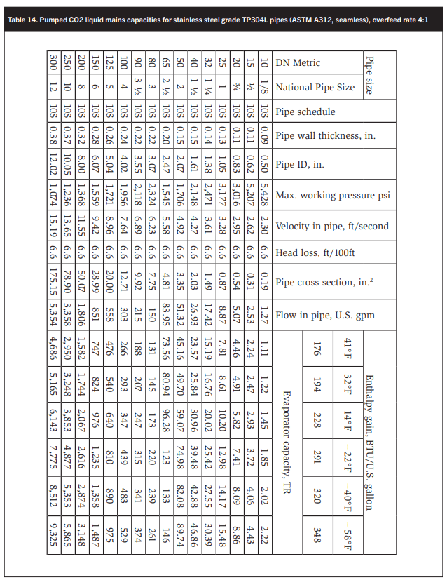
Tables 10–14 summarize the pumped liquid lines sizes for liquid recirculation (LR) rates of 1, 1.5, 2, 3, and 4 to 1. These capacities are based on a constant pressure loss of 6.6 ft/100 ft equivalent pipe length. Equivalent pipe length is defined as the length of straight pipe to which the equivalent lengths of all valves, strainers, bends, tees, impact of branch connections, etc., are added. Table 9 lists these equivalent length factors. The equivalent pipe length is the factor multiplied by the valve or fitting size in feet.
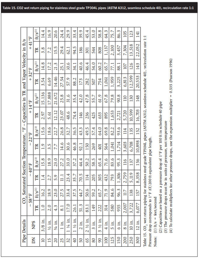
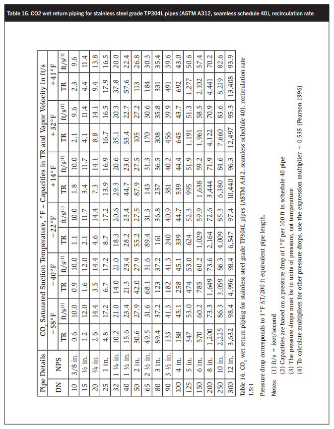
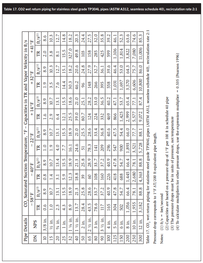
Tables 15-18 show wet return line sizes for LR rates of 1, 1.5, 2, and 4 to 1. These calculations are based on basic software developed by Stefan Jensen in 1986 and updated by the author’s collaborator and scientific supporter John Ball.

Using the tables sizing compressor discharge lines, liquid drain lines from the receiver, liquid lines from the receiver to the +41°F vessel to the +32°F AC/parallel compressor suction trap, and from there to the intercooler and pump suction lines is not possible.
EVALUATION OF CO2 COMPRESSOR MASS FLOWS AND VAPOR DISPLACEMENT
To calculate the high-pressure liquid lines we need to know the mass flows in the liquid lines. In Table 19 the mass flows to the 41°F AC/compressor suction trap, the +23°F chiller accumulator/intercooler, and the −31°F freezer accumulator are evaluated as are the CO2 vapor volumes generated. The approximate ammonia swept volumes at identical conditions are determined and compared with the calculated CO2 swept volumes.
In Table 1 the capacity of a 57 cfm subcritical CO2 compressor is nine times greater than the ammonia capacity of the same compressor at identical operating conditions. In Table 9 a CO2- to-ammonia swept volume ratio of 7.61 is calculated at an 11°F lower saturated suction temperature. The difference is most likely due to the author assuming a lower volumetric efficiency.
At 85% volumetric efficiency the calculated swept volumes of the AC and high- stage CO2 compressors are about 5% greater than those quoted for well-known, commercially available semihermetic trans- and subcritical CO2 compressors. The author is therefore confident in the results of the tabulated calculations in Table 19.
The data in Table 19 has been used to size all the compressor discharge headers shown in Table 20. The compressor discharge temperatures were taken from manufacturers’ compressor data and the CO2 velocities in the lines were assumed as reasonable values.
LIQUID PUMP SUCTION LINES
Pearson (2005) makes a compelling case for a 2:1 LR rate in terms of air-cooling evaporator efficiency enhanced by high mass velocities in long evaporator circuits at a moderate pressure drop. Pearson (2005) also presents the results of the excellent performance of a CO2 plate freezer with a recirculation rate of 4:1.
As in the case of beef chilling, an LR ratio is chosen such that peak heat loads may exceed average heat loads by as much as 75%. In such a case a 2:1 LR rate still delivers a wet evaporator exit vapor at a quality of 88%.
With the current development of evaporator exit vapor quality sensing methods, regulating liquid supply to evaporators over a widely fluctuating capacity range generated in process refrigeration systems will be possible.

Cavitation is always a risk in the suction lines of refrigerant circulating pumps. So it is recommended that CO2 liquid velocities in pump suction lines do not exceed 80 ft/ min ±10%.
The pump capacities may be obtained from Tables 8–12 for the relevant LR rate; in this case, Table 10 for the chiller pump and Table 12 for the 4:1 LR ratio to the plate freezers and cold store. See Table 21 for the liquid pump suction sizes.
EQUIVALENT HIGH-STAGE COP
In conventional two-stage ammonia systems used in meat packing plants (MPPs), no parallel compression (PC) is present and the process area cooling (PAC) is provided by the high-stage (HS) compressor. Arguably then, the effective high-stage capacity in this case is equal to the high-stage capacity plus the process area cooling refrigeration, i.e., 636 TR + 244 TR = 880 TR. See Item 4 in Table 22.
The equivalent power consumption includes the PC energy consumption given a total of 233 + 158 + 546 BHP = 937 BHP. Thus the BHP/TR equals 937 BHP ÷ 880 TR = 1.065. Thus the equivalent COP is 4.7162 ÷ 1.065 = 4.43. This compares satisfactorily with a COP of 3.9 for ammonia at 17.6°F SST and 95°F SCT. See Figures 19 and 20. In Figure 20 the CO2 COP is shown much higher at about 5.87 but the reality is that the energy consumed in parallel compression, i.e., 158 BHP in Table 2, is an energy subsidy to improve the COP of the high-stage compressor, thus a real COP of 4.93 applies in this case.
OIL RECOVERY
Ultimately all oil entering the system will end up in the low-pressure receiver (LPR). Unlike in the case of ammonia, oil needs to be distilled out. To reduce the energy input and resulting heat load from such oil distilling processes, the heat source for oil distilling is provided by 32°F liquid flowing the 32°F suction trap (20) to the 23°F high-stage accumulator/intercooler (Item 22 in Figure 18). Oil is then recycled to a head pressure tank for reuse in the compressors. The ultimate degree of oil recovery should be a minimum as the benefit of the liquid subcooling only partially offsets the energy consumption of the booster and the associated high-stage load.
That the oil separation practices applied in the compressor discharges be of the highest performance and best practice is important.
PRESSURE VESSEL DESIGN
Bent Wiencke has written the definitive conclusive manual on the sizing and design of gravity separators for industrial refrigeration (2010, 2011). His clear conclusion is that the separation velocities for CO2 are considerably lower than those for ammonia.
Consider a vapor stream in which liquid droplets are entrained. Several forces act on the suspended liquid droplets as follows:
- Gravity pulls the droplet down.
- Buoyancy supports the droplet.
- The drag force exerted by the vapor stream prevents the droplet from dropping.
- The friction force resists a liquid droplet falling down from an upward vapor velocity.
See also Stoecker (1960) for an excellent paper on this matter.


In this particular case there are three compression cycles:
- AC/parallel compression for a CO2 DX system at an evaporating temperature of 32°F.
- High-stage compressors serving as the compressors for the chilling loads and the second stage for the booster compressors at an evaporating temperature of +23°F.
Booster compressors to provide capacity for the plate freezers and cold store at an evaporating temperature of −31°F.
In Table 23 separation velocities of 25, 25, 30, and 40 ft/min were selected for the 32°F AC compressor suction trap, the +23°F accumulator/intercooler, the low pressure receiver, and the oil still separator. The CO2 liquid-to-vapor density ratios for +32, +23, and −31°F are 9.5, 11.5, and 35:1 respectively. The NH3 liquid-to-vapor density ratios for the same temperatures are 184, 233, and 531:1. This shows that separating liquid droplets from an ammonia vapor stream is much easier than from a CO2 vapor stream.
In the case of the LPR the separation velocity is not relevant as the LPR acts as the system receiver as well as the freezer accumulator. Based on that we advocate the use of all liquid separation techniques in a design, i.e., impingement, change of direction, and centrifugal.
BENEFITS AND DISADVANTAGES OF WATER HEATING BY CONDENSING CO2
Using the heat rejection from high-stage and AC parallel compressors has significant advantages in meat production facilities like beef, pork, and poultry plants, which consume large volumes of hot water for processes like sterilization and scalding prior to defeathering of chickens and dehairing of hogs. Hospitals and hotels also use large volumes of hot water and would benefit from CO2 AC for cooling and heating and hot water production (Visser 2014c, 2015b, 2016).
The advantages are:
- Significant fuel energy cost reduction for hot water production.
- Significant reduction in condenser water consumption, including water treatment chemicals and disposal of bleed water to sewer or effluent treatment system.
- Reduction in CO2 global warming emissions (GWE) due to reduced gas consumption. • High degree of liquid subcooling by preheating water in a heat exchanger in the liquid feed brine to the DX suction trap.
- Reduction in booster discharge temperature to the intercooler by preheating water and superheating the suction vapor to the AC/parallel compressors to achieve a high enough discharge temperature for water heating. This reduces the booster discharge heat load by 87 kWR from 490 TR to 403 TR. This represents a reduction of 12% in the total high-stage heat load of 723 TR to 636 TR.
The disadvantages are:
- The need for a large-capacity hot water storage tank at a temperature of 150°F.
- Cost of high-pressure CO2-to-water heat exchangers. This cost would be offset by the cost of a gas-heated hot water plant.
- The need for a controlled AC and high-stage CO2 compressor discharge temperature to a minimum of 160°F to achieve an exit water temperature of 150°F. This requires the suction superheat be lifted to approximately 15°F in the case of both the high-stage and AC compressors. The result of the increased superheat is a reduction in the compressor cooling COP of 3% and 1%, thus a small increase in electrical energy consumption of the CO2 compressor occurs.
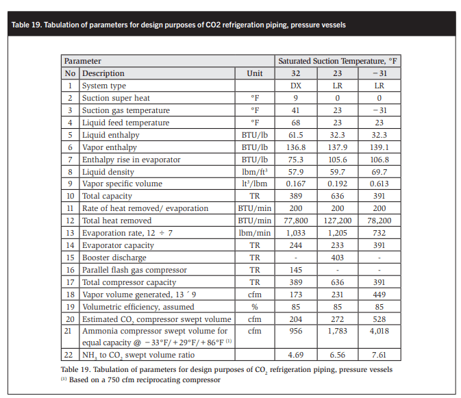
Table 24 and Figure 21 show the performance of a high-stage CO2 compressor as a water-heating heat pump in terms of the variation in evaporator and compressor capacities, COPs, and discharge temperatures with increasing suction super heat. Table 25 and Figure 22 show the performance of an AC/parallel CO2 compressor.
An advantage of CO2 compressors is that at 86°F saturated condensing temperature 68% of the heat rejected is sensible heat with only the remaining 32% of the heat as latent heat. See Figure 23.
In Table 26 the four types of heat recovery are evaluated. Note that the heat rejection from the booster discharge reduces by 51 TR or 8%.
The calculated total heat generated is 145.6 therms per hour, i.e. say availability 140 therms/hour at design conditions. This will vary with load, and compressor superheat level and rate of water flow need to be tightly controlled. See Figure 21.
As shown in Table 25, at design conditions sufficient heat is available to heat 320 U.S. gallons of water per minute from the mains water temperature of 59°F to 150°F in four stages as shown in Figure 24. This process not only saves considerable amounts of gas, but also evaporative condenser water.

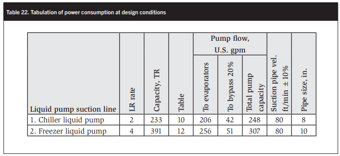

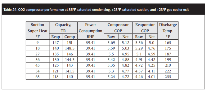
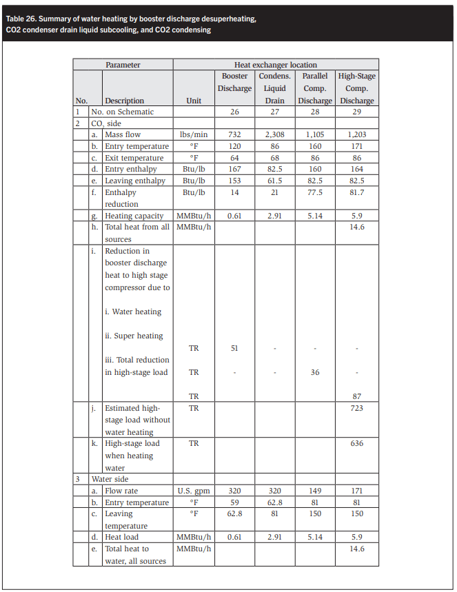
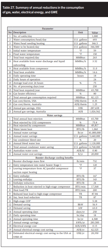

Table 27 summarizes the annual reductions in gas and water consumption.
SUMMARY OF SOUND INDUSTRIAL CO2 REFRIGERATION SYSTEM DESIGN BASED ON AMMONIA SYSTEM DESIGN PRACTICES
In the previous sections an effort was made to explain that applying CO2 in industrial and most other refrigeration applications has a great deal of merit and is not all that different from designing an industrial ammonia refrigeration system.
The following steps are involved:
- Determine various heat loads in the system.
- Select a refrigerant supply system: DX, flooded (FL), or LR.
- Select evaporating temperatures for various sections like process area cooling with glycol brine; process product chilling, e.g., hot boxes; and process product freezing such as spiral, blast, and plate freezers.
- Design evaporators in house or select suitable air coolers from manufacturers’ data. Generally CO2 evaporators have considerably less surface area than equivalent capacity ammonia evaporators with equivalent circuit pressure drop expressed in boiling point temperature reduction along the refrigerant circuit. In all applications the suction take-off from the evaporator should be from the lowest point suction header in the evaporator.
- Select defrosting method. Both hot gas and electrical defrost are suitable, as is warm glycol generated by heat recovery from the booster or high-stage compressors. The glycol tube circuit would ideally comprise one glycol tube for every four refrigerant tubes. Drain tray heaters are required in all cases, except where water defrost is applied.
- Lay the refrigerating system out on the plan of the facility.
- Size the liquid supply piping for the various DX and/or LR operations.
-
- Select DX liquid piping at an LR ratio of 1:1 in Table 8.
- In the case of highly variable refrigeration loads such as batch loaded hot boxes, the peak heat load can exceed the average heat load by 50 to 75%. Select liquid piping at a LR ratio of 1.5 to 2:1 from Tables 9 and 10.
- In the case of steady process freezing and cold storage loads select piping at LR ratios of 1:1 to 1.5:1 from Tables 8 and 9.
- Plate freezers may require a higher circulation rate depending on the plate construction, circuit length, and heat flux. Circulation rates of 2:1 to 4:1 are to be expected. See Tables 10–12. Plate freezer CO2 LR rates are considerably lower than those used for LR ammonia refrigerated plate freezers.
-
- When the CO2 flows are known, liquid pumps may be selected using water flow piping design data as the dynamic viscosity of CO2 is about the same as the dynamic viscosity of water at 68°F.
CO2 pump pressures must be considerably higher where backpressure valves are used to regulate evaporating temperatures because the pressure gradient per degree F for CO2 is much greater than the same for ammonia. For example, the saturation pressures for ammonia at +23°F and +30°F are 37.5 and 48.5 psig respectively, i.e., an 11psi difference. The CO2 saturation pressure are 433 and 498 psig respectively at +23°F and +30°F, which equates to a pressure difference of 65 psi, or nearly six times as high as that for ammonia. A CO2 liquid pump would need to overcome this extra back pressure and thus must be able to perform at a much higher differential pressure. Furthermore, at high evaporating temperatures, CO2 mass flows/ TR are quite low compared with ammonia, and thus the energy consumption of a CO2 liquid pump is expected to be much greater than that of an ammonia liquid pump. This is because the energy consumption of a liquid pump is a function of mass flow multiplied by the differential pressure plus static lift and piping friction. Additionally, the energy consumed by a liquid pump is a parasitic heat load in the system, and thus in the case of a CO2 liquid pump this parasitic heat load would be higher leading to higher energy consumption. The next thing to watch is pump cavitation, and we recommend that the available NPSH is at 1.5 times the required NPSH at the pump duty point at the minimum expected operating level, i.e., low-level alarm.
Based on this, DX operations are much preferred. When CO2 evaporator exit quality sensors (EEQS) become available the need for pumped systems may be much lower. EEQS would also assist minimum charge CO2 systems similar to the EEQS’s impact on ammonia systems.
It is also recommended that the pump minimum CO2 flow without any consumption in the system be 20% of the system consumption to ensure the CO2 pump does not cavitate at low flow.
Ensuring that the CO2 velocity in the main drop leg from the accumulator does not exceed 80 ft/min at full flow, i.e., 120% of system evaporation rates, is also desirable. - Size dry suction and wet return piping corresponding to the liquid feed rates. Determine equivalent length return piping by adding the equivalent length of all bends, tees, valves, and strainers according to Table 17. NPT size is in ft, e.g. 6 in. = 0.5 ft. A good rule of thumb is that CO2 suction piping has about half the diameter of ammonia piping with the same capacity. Like in ammonia systems, suction piping should slope down to the suction traps or pump accumulators to assist oil return.
- Once total refrigeration capacities are known they are divided into three categories:
-
- Process area and AC refrigeration and general AC loads suitable for DX operation at 30–32°F without any defrost requirements. The saturated liquid supply temperature would be 41°F.
- Refrigeration loads generated by process chilling at operating temperatures of 30–35°F with a liquid supply temperature of 20–23°F. The boosters to the interstage would contribute the other refrigeration load.
- Refrigeration loads generated by cold stores and process freezers at evaporating temperatures of −30 to −40°F or lower.
-
- Compressors and boosters can now be selected as follows:
-
- Calculate the CO2 mass flow for the aforementioned three refrigeration duties at 32, 23, and −30 to −40 at the respective liquid feed temperatures.
- Add the economizer load of the high-stage compressor to the AC compressor. This equates to the mass flow to the high-stage compressor multiplied by the enthalpy reduction in the liquid flowing from the liquid receiver or water-cooled liquid subcooler to the first-stage expansion vessel operating at about 40°F saturation temperature.
-
- Now that AC/parallel, high, and booster sizes are known, calculate the minimum diameter of suction traps, intercoolers, and low-side suction accumulation using CO2 vapor velocities of about 25–30 ft/min for high-stage vessels and 35–40 ft/ min for low-stage vessels. In reality CO2 vessels have about half the diameter of equivalent capacity ammonia vessels.
- The pilot CO2 liquid receiver should hold 1 minute liquid CO2 supply as operating charge and its volume is two to two and a half times the operating charge volume.
- Because of the high CO2 pressures, the intercooler is recommended to be made the low-pressure liquid receiver. In such a case, the low-temperature refrigeration would be CO2 DX.
- In the case of plate freezers the pump accumulator would become the low- pressure receiver because the liquid charge fluctuations in LR plate freezers correspond to about 80% of the internal plate volume.
- The total system charge needs to include the charge in the evaporative condenser/gas cooler.
- Using an evaporative condenser for ambient wet bulb design temperatures up to 77°F is quite feasible. This is simply the most important adoption of standard ammonia technology.
- At higher wet bulb temperatures up to 82.4°F (28°C) an evaporative gas cooler will cool transcritical CO2 to a gas cooler exit temperature of 86 to 87.6°F (30 to 31°C) and at such gas cooler exit temperatures CO2 refrigeration is quite efficient and compares favorably with ammonia, HFCs, and hydrocarbons applied in hot, humid climates. Please note that the 1% incidence ambient wet bulb design temperature is not exceeded in 98% of the world’s climates.
- Oil separation requires special attention. In the first instance every effort should be made to prevent oil entering the system by using high-efficiency oil separators. Where possible use DX applications for all low-temperature loads. Oil will ultimately arrive at the end of the system. A properly sized suction trap will collect the oil, which may then be drained to an oil drain vessel often passing through a PHX heated by warm liquid from the interstage. This liquid passes first through a coil in the oil drain vessel from where it flows through the PHX. After the PHX the warm liquid flows through a coil in the lower dished end of the vertical suction trap before flowing to the low-temperature evaporators (LTEs). Thus the evaporation of CO2 entrained in the oil provides a degree of liquid subcooling, and consequently the energy consumption of this system is not adversely affected to any great degree, if at all.
- In the case of LR systems for lowtemperature work, distilling the oil from the system is necessary. This is again accomplished by using warm CO2 liquid flowing to the Intercooler/high-stage accumulator (IC/ HSA) to evaporate a portion of lowtemperature liquid from the freezer liquid pump discharge. The subcooling of the liquid flowing to the IC/ HSA enhances the COP of the highstage compressors, but the extra load added to the booster may be quite energy intensive. Therefore, the amount of LT liquid evaporated to remove the oil from the system should be an absolute minimum and be based on the ammonia oil recovery principle that the amount of oil removed from the system must equal the amount of oil added to the system.
- Flooded evaporators. This is feasible but at this stage the amount of liquid head required above the top of an evaporator to get an effective thermosiphon operating is unknown. CO2 vapor has a much higher density than NH3 vapor, and CO2 liquid is also more dense than NH3 liquid. So establishing an ammonia thermosiphon is easier. Furthermore, distilling oil from a surge drum on say a CO2 refrigerated flooded air cooler would be necessary. This is technically possible but a little cumbersome. In the case of hot gas defrost, any CO2 condensed during defrosting would need to be evaporated before transferring any oil. However, automatically removing any oil from a surge drum after it has been completely pumped down for a defrost may be possible. The author will try a flooded CO2 system to chill water for office AC fan coil units and will know in about six months how effective the operation is. The standby option is DX on the same CO2 flooded PHX water chillers.
- The large potential for heat recovery from CO2 systems should not be understated in food-processing applications where a lot of one pass hot water is used and in hotels and hospitals.
Hopefully, this summary of how to design a multifunction two-stage sub- or transcritical CO2 refrigerating system with parallel compression (MF2STCCO2SPC) is beneficial. Apart from oil recovery, there are very few basic differences between conventional LR ammonia and MF2STCCO2SPC systems. CO2 systems’ suction piping and pressure vessels are about half the diameter of those for ammonia. Particularly at elevated evaporating temperatures, CO2 liquid lines are larger than ammonia liquid lines.
CONCLUSIONS
The inevitable conclusion is that CO2 is a good refrigerant suitable for use in industrial refrigerating systems if evaporative condensers/gas coolers (EC/GCs) are used, just like evaporative condensers are used as standard equipment in ammonia plants.
In many food-processing industries simultaneous requirements exist for refrigeration and hot water—beef and hog processing, chicken processing, etc.- which is not recyclable. Such single-pass process hot water is heated from mains water temperature to 150°F to 185°F for cleaning and sterilization purposes respectively and is disposed to waste after use.
The high operating pressures of CO2 are an advantage when using EC/GCs as reducing the condensing temperature to about 12 to 15°F above the ambient wet bulb temperature is possible. This results in low condensing pressure and substantial improvements in COP and thus energy savings.
An AWBDT of 82.4°F is not exceeded in 98% of the world’s climates. At this high AWBDT reducing the gas cooler exit temperature to 86 to 87°F is possible, and at such relatively low CO2 gas cooler exit temperatures the compressor COPs for transcritical operations at 1,100 to 1,200 psi are still quite high and compare reasonably well with the COPs of ammonia high-stage compressors operating at saturated condensing temperatures of 100 to 105°F when using evaporative condensers in highhumidity climates.
Without doubt well-designed CO2 refrigerating systems using EC/GCs operate efficiently in all climates, which will lower the so-called “CO2 equator” from the Northern Mediterranean Sea to the geographical equator.
As a rule of thumb, CO2 vertical pump accumulators and suction traps are about half the diameter of equal capacity ammonia pump accumulators and suction traps. But other requirements for the sizing of such vessels—surge volume, ballast, separation distance—frequently mean that CO2 and ammonia vessel sizes are not a lot different, and thus operating vapor velocities in CO2 vessels are quite a bit lower than the maximum permissible vapor velocities to ensure adequate liquid separation from the vapor stream.
CO2 wet return lines are about half the diameter of ammonia wet return lines of the same capacity with the same boiling point suppression.
At CO2 evaporating temperatures between 12 and 10°F the pumped liquid and wet return lines are about the same size, which is surprising.
At CO2 evaporating temperatures of −20 to −40°F the pumped liquid lines are one to two sizes smaller than the wet return lines. For example at −40°F and a liquid recirculation of 2:1 a 4 in. wet return has a capacity of 226 TR. A 2 ½ in. liquid line has a capacity of 266 TR. A 2 in. liquid line may also be adequate with a rated capacity of 164 TR. The higher the oil consumption, the higher will be the energy requirement to distill the oil from the system. High-quality oil separation is therefore essential.
CO2 refrigeration applied to the cooling and heating of buildings shows a good deal of promise, both for retrofitting and in new buildings. In new buildings CO2 may also be used for zonal firefighting, avoiding the need to turn off the power supply to a building in case of fire for firefighters’ safety. Lifts would remain operational and water damage to the building, frequently much greater than the fire damage, would be reduced.
CO2 cooling and heating systems are particularly suitable for installation into hospitals and hotels, both of which use large quantities of hot water.
In summary, CO2 has the potential to become the most ubiquitous refrigerant for all manner of applications from domestic heating and cooling, to refrigeration and freezers, to mobile air conditioning and all food processing and cold storage, to the largest district heating and cooling systems.
However, much larger compressors are required. Atlas Copco, General Electric, and some others have multistage compressors for natural gas compression up to 11,000 psi and pressurized crank cases up to 900 psi. Reconfiguring the piston and cylinders for CO2 is not a difficult job. Indeed, having different cylinder and piston configurations for different gases and stages is quite common. As an industry, approaching these large companies may be desirable, although the author’s efforts to date have failed.
ACKNOWLEDGMENTS
We gratefully acknowledge the assistance and support received from the following people, which greatly assisted the satisfactory completion of this paper:
Bent Wiencke for sending his papers “Fundamental Principles for Sizing and Design of Gravity Separators” (2011) and “Computing the Partial Volume of Pressure Vessels” (2010).
Stefan Jensen for sharing his 1986 three-page computer program to calculate the wet return line pressure drop for ammonia. This invaluable piece of work was updated by John Ball using the latest data and technology. I am indebted to Mr. Ball for producing a very valuable piece of proprietary software permitting calculation of pressure drops in CO2 wet return lines and other refrigerants, as needed.
Forbes Pearson for sharing his “Use of Carbon Dioxide for Air Conditioning and General Refrigeration,” IIR Sustainability of the Cold Chain Conference, Cambridge, UK, 2010.
In addition, the author is grateful to Eric Smith of IIAR, who was kind enough to send the thermophysical data of the refrigerant CO2 in imperial units without which completing this paper would not have been possible.
REFERENCES
Ball, J. and Visser, K. (2015). “The global application of efficient CO2 refrigeration enabled by evaporative condensers and gas coolers.” IIAR Industrial Refrigeration Conference and Exhibition, San Diego, CA, 22–25 March 2015.
GEA Grasso. (2001). PowerPoint presentation at C-Dig meeting, Berlin, March 2.
Kriezi, E. et al. (2015). “Multi ejector and impact of ejector design on the operation of a CO2 refrigeration system”. 6th IIR International Conference: Ammonia and CO2 refrigeration technologies. Ohrid, Macedonia, 16-18 April 2015.
Lorentzen, G. (1993.) “Revival of carbon dioxide as a refrigerant—Refrigeration beyond the crisis.” Inst. of Refrigeration, London.
Minetto, S. et al. (2015). “Air conditioning and space heating with CO2: efficiency and improvement with ejector”. 6th IIR International Conference: Ammonia and CO2 refrigeration technologies. Ohrid, Macedonia, 16-18 April 2015.
Pachai, A.C. et al. (2001) “CO2—Yesterday’s buzzword—Today’s real refrigerant.”
Pearson, A.B. (2005). “Evaporator performance in carbon dioxide systems.” Technical Paper #10, IIAR Ammonia Refrigeration Conference and Exhibition, Acapulco, Mexico.
Pearson, S.F. (1992). “Development of improved secondary refrigerants.” Proc.Inst.R, 93,7–11.
Pearson, S.F. (1996). “Applications of carbon dioxide in industrial refrigeration.” Nestle Refrigeration Workshop, Bjuv, Sweden.
Pearson, S.F. (2010). “Use of carbon dioxide for air conditioning and general refrigeration.” 1st IIR Conference on Sustainability and the Cold Chain, Cambridge, UK, 29–31 March 2010.
Petterson, J. et al. (1995). “Recent advances in CO2 refrigeration.” IIR B2, Theme 4, 19th International Congress of Refrigeration at The Hague, August 20–25, pp. 961– 968. Stoecker, W.F. (1960.) “How to design and operate flooded evaporators for cooling air and liquids.” Heating, Piping & Air Conditioning, December 1960.
Stoecker, W. (2000.) “Ammonia/carbon dioxide hybrid systems: Advantages and disadvantages.” IIAR 22nd Annual Meeting, Nashville, TN, USA, March 19–22, 2000.
Svariegaard, C. (1996.) “CO2 as a refrigerant.” Nestle Refrigeration Workshop, Bjuv, Sweden, September.
Visser, K. (2012). “A progress report on the world’s first multi-function two stage transcritical CO2 refrigeration system.” 10th IIR Gustav Lorentzen Natural Refrigerants Conference, Delft, the Netherlands, 25–27 June 2012.
Visser, K. (2014a). “A desk top study on the application of evaporative condensers for subcritical CO2 condensing.” 3rd IIR International Conference on Sustainability and the Cold Chain, London, 23–25 June 2014.
Visser, K. (2014b). “The application of evaporative condensers for subcritical CO2 condensing and transcritical CO2 gas cooling.” ATMOsphere America, Business Case: Natural Refrigerants, San Francisco, 18–19 June 2014.
Visser, K. (2014c). “The case for natural refrigerant CO2 in commercial buildings, hospitals and supermarkets in Melbourne to drive significant reductions in energy and cooling water consumption and both indirect and direct emissions.” Presentation to 2nd Chinese Government Delegation, RMIT University, Melbourne, 25 September 2014.
Visser, K. (2014d). “The case for natural refrigerants including some examples for CO2 in commercial buildings, hospitals and supermarkets in Melbourne.” CCN Live: Profiting in the Green Age, Sydney, 13 August 2014.
Visser, K. (2015a.) “CO2 evaporative condensers and gas coolers enable efficient CO2 refrigeration application worldwide irrespective of climate.” 6th IIR International Conference: Ammonia and CO2 Refrigeration Technologies, Ohrid, Macedonia, 16–18 April 2015.
Visser, K. (2015b.) “The efficient use of subcritical CO2 refrigerating systems for cooling with on demand heating in transcritical mode.” 3rd International Symposium on Energy Challenges & Mechanics, Aberdeen, Scotland, 7–9 July 2015.
Visser, K. (2016). “Building cooling and heating with transcritical CO2 system reduces energy and cooling water consumption and CO2e emissions.” 4th IIR International Conference on Sustainability and the Cold Chain, Auckland, New Zealand, 7–9 April 2016.
Wiencke, B. (2010). “Computing the partial volume of pressure vessels.” Int. Journal of Refrigeration, 33(2010), 868–876. Doi:10.1016/ ijrefrig.2009.11.009.
Wiencke, B. (2011). “Fundamental principles for sizing and design of gravity separators for industrial refrigeration.” Int. Journal of Refrigeration, 34(2011), 2092– 2108. Doi:10.1016/j.ijrefrig.2011.06.011.