2024 Technical Paper #8
Controlling the Circulation Rate in Ammonia Refrigeration Systems
Author: Morten Juel Skovrup, Global Applications Manager; Niels P. Vestergaard, Global Applications Expert; and Roozbeh Izadi-Zamanabadi, Lead Expert, Control Engineering, Danfoss A/S
Abstract
Reducing the charge in ammonia refrigeration systems is becoming increasingly important. However, reduction must be achieved without compromising the efficiency of the ammonia refrigeration system.
Reducing the refrigerant charge in an ammonia refrigeration system requires that either the circulation rate in a pump circulation system is controlled (i.e., a controlled circulation rate (CCR) system) or the refrigeration system is changed to a direct expansion (DX) refrigeration system. In the case of a DX system, the efficiency of the refrigeration system must be maintained by reducing the superheat in the evaporators as much as possible, or by operating the evaporator slightly flooded, known as a wet DX (WDX) system.
This paper focuses on recent laboratory and field tests dealing with measurement and control principles, which can be used to control both CCR and WDX systems. The solution consisting of a sensor, electronic controller, and control valve can be used to control the circulation rate in a pump circulation system (i.e., traditional pump overfeed system) operating under both full and partial loading, enabling control of the evaporator outlet in a WDX system and safe management of the amount of liquid returning from the evaporator
Introduction
When designing an industrial ammonia refrigeration system, the ammonia refrigerant charge is an important factor not only for system operation but also for system safety. If the ammonia refrigerant charge is high, risk assessment becomes increasingly difficult, and at a certain charge limit (varying from country to country), the requirements established by local authorities also increase. However, by minimizing the ammonia refrigerant charge while ensuring satisfactory operation, the risk assessment and requirements from authorities become easier to handle. If we consider a traditional ammonia pump circulation system (i.e., a typical traditional pump overfeed system) as the reference state, with uncontrolled liquid feed and a design circulating rate of 3–4), then there are several ways to reduce the charge, for example:
- Build the refrigeration system as an indirect system, circulating a secondary refrigerant on both the hot and cold sides. This makes the ammonia refrigeration system compact and ensures a very low refrigerant charge, but it also increases energy consumption because of the extra temperature differences introduced by the secondary refrigerant heat exchangers.
- Build the refrigeration system as a direct expansion (DX) system, avoiding the recirculation of the liquid refrigerant. This brings the refrigerant charge down significantly but requires a certain amount of superheat at the evaporator outlet to stop the liquid refrigerant from returning to the compressor (i.e., slugging). To create this superheat, the system needs to run with a lower evaporation temperature, again compromising energy efficiency.
There are several other ways to reduce the ammonia refrigerant charge, but most attempts are centered around:
- Reducing the amount of liquid refrigerant in the lines heading to evaporators.
- Reducing the amount of liquid refrigerant in the lines coming from evaporators.
- Making compact systems – for example, by building penthouse units instead of having a central machinery room.
In any case, the first requirement for a low-charge ammonia refrigeration system is to have the same or better energy efficiency than the reference system, namely the traditional pump (overfeed) circulation system.
This paper focuses on reducing the ammonia refrigerant charge by:
- Controlling the circulation (overfeed) rate in pump circulating systems.
- Controlling the mass flow of refrigerant to DX evaporators so that the evaporator is slightly flooded.
In both cases, ammonia refrigeration systems with fin-and-tube evaporators are considered.
By controlling the circulation rate in pump circulation systems, the amount of refrigerant liquid to the evaporators, the amount of refrigerant liquid in the evaporators, and the amount of liquid refrigerant returning from the evaporators can be minimized. This control method in this paper is referred to as the controlled circulation rate (CCR).
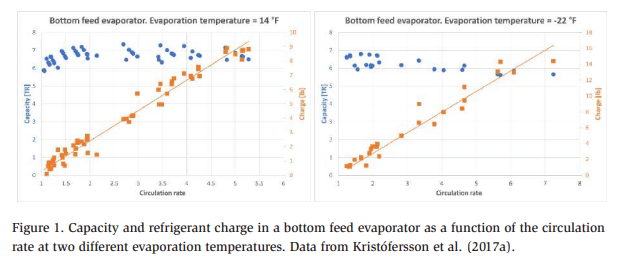
Measurements and simulations showed that the circulation rate in a modern welldesigned fin-and-tube evaporator can be brought down to almost 1.0 without compromising the capacity of the evaporator (Kristófersson et al., 2017a). In Figure 1, the measured capacity and refrigerant charge of a bottom feed evaporator are shown. The capacity is close to unchanged or even increases when the circulation rate is changed to approximately 1.2 (blue dots, left axis). At the same time, the refrigerant charge in the evaporator is reduced by approximately 85% (orange squares, right axis).
Thus, if the circulation rate can be controlled, for example, to 1.2, then the refrigerant charge in the evaporator can be minimized while preserving the capacity of the evaporator.
The mass flow is controlled in DX systems so that there is no superheat, which means that the benefits of low charge from the DX system can be leveraged, and no need for superheat implies that there will be no efficiency penalty. In this paper, such a system is called a wet direct expansion (WDX) system.
Examples of tests on both CCR and WDX systems are presented below, but first, the refrigeration systems and control solution are introduced in the following sections, starting with the traditional pump circulation system.
Traditional Pump Circulation System
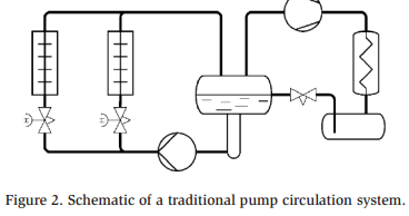
A basic diagram of a traditional pump circulation system is shown in Figure 2. The diagram shows a simple refrigeration system with two evaporators, where the refrigerant flow between the evaporators is equally distributed by adjusting the manual regulating valves. Such a refrigeration system is typically designed for a circulation rate of 3 to 4, but in reality, the circulation rate can be much higher – especially during partial load conditions.
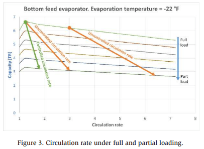
If a refrigeration system is designed for a circulation rate of 3, for example, then Figure 3 illustrates the change in circulation rate when the refrigeration system changes operation from full load to partial load:
A CCR is ideally constant when switching to a partial load, but in practice, the line on the chart tends toward a slightly higher circulation rate because it is very difficult to control the circulation rate unless a minimal amount of refrigerant liquid is exiting the evaporator. This is illustrated by the green arrow in Figure 3. However, the increase in circulation rate will be much less than the chart line for an uncontrolled circulation rate (orange arrows in Figure 3).
CCR (Controlled Circulation Rate) System
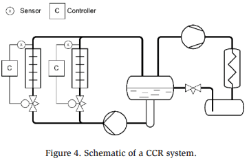
If the above pump system is designed so that the amount of refrigerant liquid exiting the evaporator is measured using a sensor, then the circulation rate can be controlled and maintained at a constant rate by replacing the manual regulating valve with a control valve, as illustrated in Figure 4.
This means that the circulation rate, and thereby the refrigerant charge, can be kept at a minimum, even under partial load conditions.
Reducing the circulation rate allows for a reduction in the size of the liquid lines to the evaporators, which further reduces the charge but also reduces the liquid carryover to the wet return lines, thus reducing pressure drops in the risers and increasing the system efficiency.
The pump separator’s size is usually determined by calculation for the non-controlled system, ensuring that there is always sufficient liquid refrigerant in the separator to compensate for load variations and liquid refrigerant accumulations during defrost. In a CCR system. The variation in the liquid refrigerant accu
WDX (Wet Direct Expansion) System
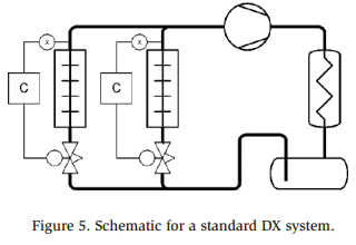
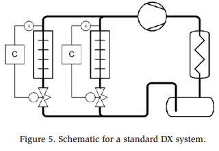
In a standard DX system, the refrigerant liquid from the condenser/receiver is fed directly into the evaporators, as shown in Figure 5.
The refrigerant charge in a DX system can be low because the pump separator is no longer required and only the required refrigerant is circulated to the evaporators.
The amount of refrigerant in each evaporator is typically controlled by maintaining a constant amount of superheat exiting the evaporator. Furthermore, the superheat is needed because the compressors require refrigerant gas and no refrigerant liquid at the suction inlet. The liquid refrigerant at the suction inlet may result in liquid slugging the compressor, potentially causing damage.
There are several requirements for the superheat:
- The temperature difference between the air and the evaporation temperature needs to be high enough to create the superheat, which means that the evaporation temperature needs to be kept at a constant value, which is generally lower than that in pump circulation systems.
- The last part of the evaporator is used to generate superheat, and as the heat transfer coefficient of the refrigerant gas is much lower than that of the evaporating refrigerant, the area of the evaporator must be sufficiently large.
If a pump circulation system is operating with a temperature difference between the air and the refrigerant of 9 to 18°F (5 to 10 K), then the DX system typically runs with a temperature difference of 18 to 27°F (10 to 15 K).
If a DX system is controlled so that the superheat is kept at 0°F or maintained with a small amount of liquid exiting the evaporator, then the evaporation temperature can be raised by approximately 9°F (5 K) compared with a standard DX system, and the energy efficiency of a DX system is typically equal to or better than that of a pump circulation system.
This is exactly what a WDX system is intended for. It uses a special sensor, which can measure the amount of liquid exiting the evaporator so that the system can be run with 0°F superheat and a minimal amount of liquid exiting the evaporator.
Because a small amount of liquid (i.e., droplets) is permitted to exit the evaporator, a suction accumulator is needed in a WDX system. In Figure 6, the suction accumulator is shown with an internal heat exchanger so that the liquid from the receiver is subcooled while the excess liquid from the evaporator is evaporated. Other arrangements for evaporating or recycling the excess liquid in the suction accumulator are possible (Nelson, 2016).
Two-Phase Flow in Evaporator Outlet
When attempting to design a sensor that can be used to measure the refrigerant condition at the outlet of an evaporator, for either a CCR or WDX system), it is important to know the two-phase flow patterns that can occur in the evaporator outlet and ensure that the flow is relatively constant within the operation range.
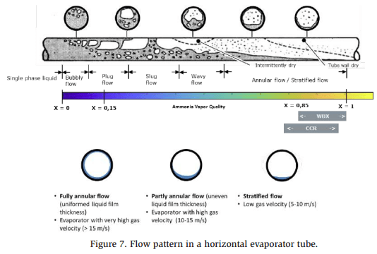
The different flow patterns in a horizontal evaporator tube are shown in Figure 7.
The ideal control range for WDX and CCR systems is also indicated in Figure 7. The typical flow pattern at the evaporator outlet is stratified flow, where ammonia liquid refrigerant flows in the bottom of the tube while ammonia refrigerant gas fills most of the tube and travels with a higher velocity than the ammonia liquid. Normally, annular flow is also expected at the evaporator outlet, but tests have shown that it is very difficult to obtain annular flow in ammonia evaporators (Cotter, 2009).
The transition between annular and stratified flow depends on the velocity of the refrigerant gas, and for ammonia, the velocity needs to be high to achieve annular flow, mainly because of the large density difference between the refrigerant gas and liquid.
This needs to be considered when designing a sensor for measuring the amount of liquid refrigerant at the evaporator outlet. It is necessary to position the sensor so that the amount of liquid refrigerant at the bottom of the evaporator tube is included in the sensor signal.
Sensor
Several technologies have been used to measure the amount of liquid refrigerant exiting an evaporator. The most common are:
- Capacitance measurements use the difference in dielectric permittivity between the refrigerant gas and the liquid.
- Radar measurements also leverage the difference in dielectric permittivity between the refrigerant gas and the liquid.
- Heated sensors rely on the difference in heat transfer coefficients between the refrigerant liquid and the gas.
In addition, more “exotic” methods using image recognition and X-rays have been attempted in laboratories.
There are multiple requirements for the sensor:
- The sensor must be able to measure refrigerant quality for many different system sizes (i.e., the sensor principle must work for a 10 TR evaporator and a 200 TR evaporator)
- The sensor must be able to measure quality under many different load conditions, including when there is ice on the evaporator.
- The sensor must be easy to maintain and service.
- The sensor measurement should not be influenced by oil.
- The sensor, together with the valve and controller, must form a plug-and-play system that can be applied to a whole range of fin-and-tube evaporators without manual adjustments.
Among the three most common sensor types, lab tests have shown that the heated sensor gives the best results for all five requirements.
The plug-and-play requirement is addressed later, in the section describing lab and field tests, but the first four requirements are addressed by the sensor position and installation.
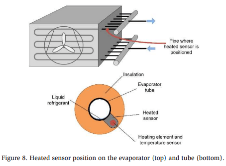
Figure 8 shows the heated sensor is placed on one of the tubes at the evaporator outlet before the manifold. Specifically, the sensor should be placed at approximately the fiveo’clock position on the tube.
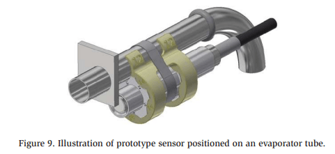
Figure 9 shows a 3D illustration of one of the sensor prototypes mounted on an Fevaporator tube at the evaporator outlet (without insulation).
The sensor consists of a fixture, a heating element, and a temperature probe (Figures 8 and 9).
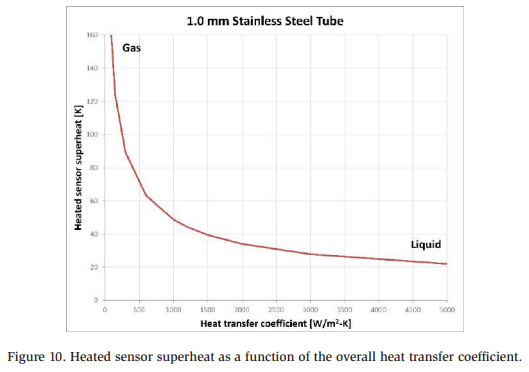
Heating the sensor means that the temperature signal is a measure of the heat transfer coefficient between the heated sensor and the refrigerant in the tube. If there is only refrigerant gas in the evaporator tube, then the measured temperature is relatively high because the difference in heat transfer coefficients between the heated sensor and the refrigerant is low, and if there is refrigerant liquid inside the tube, the temperature is much lower. Figure 10 shows a simulation of the heated sensor superheat (i.e., heated sensor temperature minus saturated refrigerant temperature) as a function of the heat transfer coefficient. In the simulations, stainless steel was used as the tube material, with a wall thickness of 1 mm.
Choosing one of the tubes of the evaporator before the manifold as the location for the heated sensor instead of at the main pipe after the manifold means that:
- The sensor will always be placed horizontally. Placing the sensor after the manifold may sometimes mean that it is placed on a vertical pipe where the flow patterns are completely different.
- There is much less variation in flow velocity and tube diameter. The variation in tube sizes for different sizes of heat exchangers is not large – a larger heat exchanger normally implies an increasing tube length and number of parallel tube runs.
- One sensor size can be used for many different evaporator sizes.
Moreover, heated sensors can be mounted outside of the evaporator tube, making it much easier to install and service them (no welding or refrigerant evacuation is required). Outside mounting also means that the sensor does not disturb the flow regime.
Control Valve
For both the CCR and WDX systems, a control valve is required to meter the refrigerant mass flow to the evaporator.
In both cases, the control valve needs to be electronically operated. Pulse width modulator (PWM) or stepper motor valves can be used, and both types have been tested in the lab. In WDX refrigeration systems, the control valve is an expansion valve based on the phase change that occurs when the liquid refrigerant passes through the valve.
Notably, a high-resolution valve is required to control the injection of ammonia liquid refrigerant into an evaporator because the energy density of liquid ammonia is high. For example, considering a standard DX system, changing the superheat by 1 K in an ammonia refrigeration system requires half the mass flow change as a system with R134a. In other words, if you have a stepper motor valve with 500 steps for an R134a system, then a valve with 1000 steps is required for an ammonia refrigeration system to obtain the same resolution in mass flow.
Control Solution
The complete low-charge control solution consists of the following elements:
- The heated sensor is shown in Figures 8 and 9.
- A pressure transmitter measures the saturated refrigerant temperature. • A temperature sensor measures the overall superheat exiting the evaporator, as explained below.
- A control valve.
- An electronic controller converts the signal from the sensors to an opening degree of the valve.
The response of the heated sensor, as shown in Figure 10, depends not only on the power applied to the heating element but also on the evaporator tube material. For example, the conductivity of stainless steel is very different from the conductivity of aluminum. Tests have shown that by adjusting the power to the heating element, it is possible to compensate for the effects of tube material.
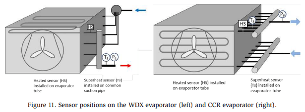
The electronic controller automatically adjusts the power applied to the heating element by monitoring the overall superheat of the evaporator. The overall superheat is measured using the pressure transmitter and a temperature sensor on the common outlet pipe of the evaporator (after the manifold) in a WDX system, or on a neighboring tube near where the heated sensor is placed on a CCR system. The positioning is illustrated in Figure 11.
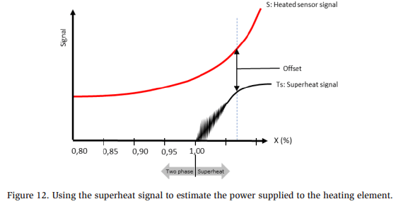
When filling the evaporator with liquid refrigerant (for example, during the initial startup, after a defrost, or after a thermostat cut-in), the controller uses the superheat signal to estimate the required power for the heated sensor.
Figure 12 illustrates the typical response of a superheat temperature sensor when the amount of superheat is decreased (going from right to left on the X-axis). From the measured superheat signal, the required power for the heating element in the heated sensor is estimated to obtain the desired offset. This offset allows the heated sensor to provide a signal that can help describe and control the outlet of the evaporator, using a two-phase area.
While estimating the power to the heated sensor, the evaporator is operating normally and providing useful cooling (i.e., in filling mode), so the estimation period is just part of the normal evaporator operation.
When the power to the heated sensor has been determined, the controller uses the heated sensor signal to optimize the evaporator’s performance. For WDX systems, the superheat is reduced so that the evaporator is operating slightly wet, and for CCR systems, the circulating rate is kept constant at a level where all evaporator runs are wet.
Application Details
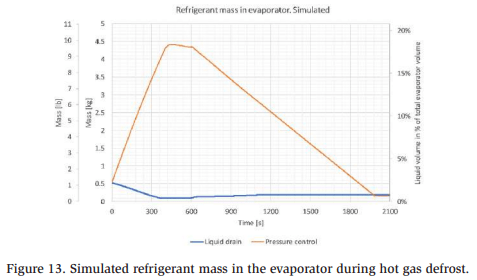
Charge reduction is an important goal when introducing either CCR or WDX systems. Therefore, it is also important to focus on the hot gas defrost system and the amount of refrigerant that is required for the selected defrost method. The liquid drain method is preferred over the drain by pressure control method to prevent refrigerant liquid from accumulating in the evaporator during defrost.
Figure 13 shows the simulated refrigerant mass in an evaporator during hot gas defrost. The results show that if pressure-controlled defrost is used, then the refrigerant mass in the evaporator builds up when defrosting starts, mainly because the evaporator is cold and almost all of the hot gas entering the evaporator is condensed (i.e., the pressure does not increase and the drain valve does not open). Vestergaard and Skovrup (2018) simulated and described the difference between the liquid drain and pressure-controlled defrost methods.
For WDX control, the control solution is prepared for handling the excess liquid refrigerant in the suction accumulator. If the liquid refrigerant level in the suction accumulator rises above a given maximum level, the controller can automatically switch to standard DX control (i.e., controlling the superheat exiting the evaporator) until the liquid refrigerant level has either dropped below the minimum level or a given amount of time has passed.
For WDX systems, it is also important to handle the water content in the ammonia refrigerant. This is not specific to WDX systems; it is also the case for standard DX systems (Nelson, 2016).
For more details on the heated sensor and the control solution, refer to the studies reported by Vestergaard et al. (2019, 2022).
Lab Tests
The control solution, including a heated sensor, valve, and electronic controller, has been tested extensively in the lab for both the WDX and CCR systems. CCR Lab Tests The control solution for CCR was tested in the lab on a standard bottom feed evaporator with a nominal capacity of 6 TR (21 kW), using ammonia refrigerant at an evaporation temperature of −31°F (−35°C). The evaporator tubes were stainless steel, with a wall thickness of 1 mm.
The evaporator was placed in a climate chamber, where it was possible to control the load by adjusting both the air temperature and humidity. The circulation rate of the ammonia refrigerant was measured using a separator after the evaporator, collecting the overfeed liquid refrigerant during the test period, which was also based on the energy balance of the climate chamber.
The temperatures and pressures before and after the evaporator were measured, as well as the mass flow of the ammonia liquid refrigerant going to the evaporator.
To validate the control solution, the following tests were performed:
- Variations in pump pressure were examined. The solution needs to be resilient to any variations in pump pressure that occur – for example, when another evaporator is cut-out.
- Variations in evaporator load were examined, including load increases – for example, when warm goods are brought into a cold room, but also decreases in load – for example, when ice is forming on the evaporator.
- Variations in evaporation temperature were examined – for example, due to compressor cut-in/cut-out.
- Tests at evaporation temperatures of 14 and −22 °F (−10 and −30°C) were performed. The properties of the ammonia refrigerant change significantly with temperature, and it is necessary to check that the control solution can still detect the evaporator outlet condition.
- Tests were performed for different temperature differences between the inlet air and evaporation temperature.
- Two different valve types were tested, namely a PWM valve and a stepper motor valve.
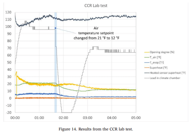
Figure 14 shows an extracted portion of the CCR lab tests where the setpoint of the air temperature is changed from 12 to 21°F (−6 to −11°C). The air temperature is controlled using a set of heating elements in the climate chamber, and the load curve in Figure 14 shows the variation in the load, keeping the air temperature relatively constant. Figure 14 shows the control algorithm used to control the heated sensor superheat, maintaining ~112°F by changing the opening degree of the control valve (in this case, a motor-operated valve). The opening degree of the stepper motor valve was slightly over 10% at the end of the test period, which means that the valve was a bit too large for the system, but still, the control was running satisfactorily.
During the lab tests, the quality of the ammonia refrigerant out of the evaporator was successfully varied between 0.70 (circulation rate of ~1.4) and 0.95 (circulation rate just above 1).
WDX Lab
Tests The control solution for WDX was tested in the lab on a standard ammonia DX evaporator with a nominal capacity of 5.7 TR (20 kW), using ammonia refrigerant at an evaporation temperature of −22°F (−30°C). The evaporator tubes were stainless steel, with a wall thickness of 1 mm.
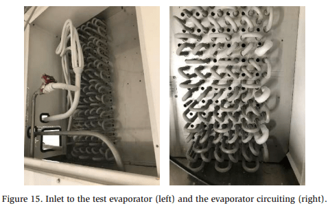
Figure 15 shows the inlet to the evaporator, including the distributor and the circuiting.
Tests conducted on the evaporator were similar to those conducted on the CCR system (i.e., the control solution was tested and the load, temperature, and humidity were systematically varied).
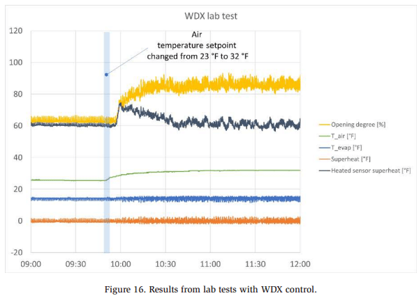
Figure 16 shows the control solution response when the climate chamber temperature setpoint is changed from 23 to 32°F (−5 to 0°C). This is practically achieved by increasing the heat load in the climate chamber. When the setpoint to the climate chamber is changed (when the load is increased), the heated sensor superheat increases, which means there is more refrigerant gas at the evaporator outlet. As a response, the controller opens the expansion valve more, and after a while, the heated sensor superheat settles at the same level as before (around 60°F) but with a higher opening degree of the expansion valve.
During the lab tests, the quality of the ammonia refrigerant exiting the evaporator was successfully varied between 0.85 and 0.95.
Field Tests
The control solution has been applied to several test sites, for both the WDX and CCR systems. Three examples of the installations and their operations are discussed below.
The shown field tests were operated on one site with the existing WDX control, called site A, and tests at site B were operated with an existing uncontrolled pump circulation system.
At both sites A and B, testing was focused on the injection of ammonia refrigerant to the evaporator. Fan control, defrost control, and thermostat control were managed using the existing programmable logic controller (PLC). The field test controller only received “cooling on/off” and “defrost start” signals from the central PLC.
WDX Field Test A.1
In field test A.1, the control solution was installed on an existing system with an aluminum evaporator in a cold room, which was a part of a larger installation. The evaporator was serving a 36°F (2°C) room and operating as a WDX evaporator. The existing system used a two-stage control, where one algorithm was used to start up the evaporator and another controlled the injection using a capacitance-based sensor. It was not possible to use the capacitance sensor during startup (for example, after a thermostat cut-out).
The evaporation temperature of the ammonia system was 5°F (−15°C).
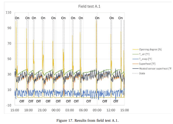
Because of the relatively high-temperature difference between the room air and the evaporation temperature, and because the load on the room was generally low, the cut-in periods of the evaporator were very short – generally less than 20 min, with “off” periods of 1 h or more (see Figure 17).
The field test revealed that the control solution handled the short “on” periods very well. The controller handled filling the evaporator after a cut-in without problems. Furthermore, the WDX mode of the controller was rarely used, mainly because filling the evaporator provided all the cooling that was needed, but when WDX mode was initiated, the control worked as intended during the short on periods. Moreover, the evaporator tube material was aluminum, which had not been tested in the lab; however, the estimation of the heat to the heated sensor worked as intended and compensated for the tube material.
WDX Field Test A.2
Field test A.2 was conducted on the same site as A.1, but with an evaporation temperature of −25°F (−31°C) in a 0°F (−18°C) room, and the control solution was the same as the one described in field test A.1 (i.e., a two-step control for filling and controlling the evaporator).
The control solution ran for 6 months, from the spring of 2023 to the autumn of 2023, without any issues.
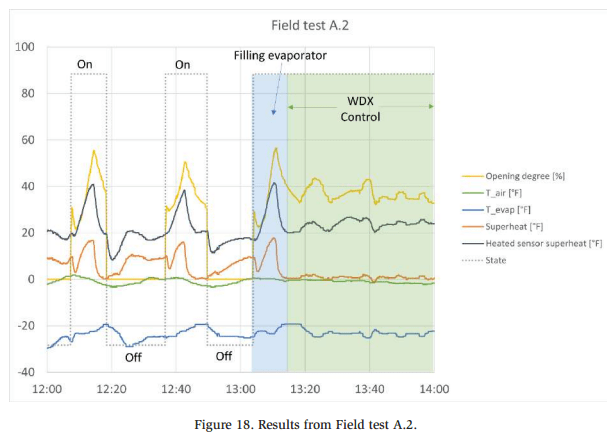
Figure 18 shows a 2 h window of the temperature measured on-site for A.2. The data starts with two relatively short on periods, where the evaporator is filled with ammonia refrigerant before the thermostat control closes for the refrigerant flow. Just after 13:00, a longer control period starts, where the superheat (measured on the common outlet of the evaporator, after the manifold) varies around 0°F (−18°C), meaning that there is liquid refrigerant exiting the evaporator. The expansion valve was an ICM stepper motor valve, and the opening degree of the valve is shown in Figure 18.
CCR Field Test B
For field test B, the control solution was installed on an evaporator in a pump circulation system. This included changing the manual control valve at the inlet to the evaporator to an ICM stepper motor valve.
The evaporator was operated with an evaporation temperature of approximately −31°F (−35°C) and an inlet air temperature of −4°F (−20°C). The evaporation temperature varied significantly for this system, as any compressor cut-in and cut-out greatly affected the system capacity.
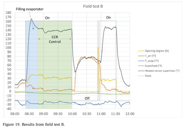
Figure 19 shows a 4 h extract of the measured temperatures from field test B. In the first on period, starting just before 8:30, the evaporator is filled with ammonia refrigerant and then the CCR control takes over. The superheat measurement is performed on the tube neighboring the one where the heated sensor is installed (see Figure 11), and the superheat is close to zero, meaning liquid refrigerant is exiting the tube. Throughout the CCR period, the controller keeps the heated sensor superheat at ~140°F (60°C), effectively controlling the liquid refrigerant injection into the evaporator.
The off period starting at approximately 10:00 in Figure 19 is probably a defrost period. A short on-signal is sent to the controller at the end of the defrost period for unknown reasons. The controller reacts by opening the control valve before an offsignal is sent shortly thereafter, followed again by another on-signal. Despite these fast on/off signals from the central PLC, the control solution has been running at the test site for several months without any issues.
Conclusion
A new solution for controlling the circulation (overfeed) rate of ammonia in finand-tube evaporators has been developed. The solution consists of a heated sensor, a control valve, and an electronic controller. The solution has been tested under laboratory conditions and in the field.
For existing standard evaporators, laboratory tests have shown that the circulation rate can be reduced to ~1.2 without compromising the capacity of the evaporator.
The control solution has been tested in the field, on evaporators operating under difficult conditions, from a control point of view. In all cases, the solution has been working as intended from the moment it was initiated.
References
Cotter, D., 2009. Improvement of the Heat Transfer Performance of an Ammonia Air Cooler. London South Bank University.
Kristófersson, J., Vestergaard, N., Skovrup, M., Reinholdt, L., 2017a. Ammonia charge reduction potential in recirculating systems – Calculations, in: Proceedings 7th Conference on Ammonia and CO2 Refrigeration Technologies. Presented at the 7th Conference on Ammonia and CO2 Refrigeration Technologies, Ohrid.
Kristófersson, J., Vestergaard, N., Skovrup, M., Reinholdt, L., 2017b. Ammonia charge reduction potential in recirculating systems – System benefits, in: Proceedings 7th Conference on Ammonia and CO2 Refrigeration Technologies. Presented at the 7th Conference on Ammonia and CO2 Refrigeration Technologies, Ohrid.
Nelson, B.I., 2016. DX Ammonia Piping Handbook 4th Edition. Vestergaard, N., Skovrup, M.J., 2018. Energy and Function Analysis of Hot Gas Defrost in Ammonia Refrigeration Systems, in: Technical Papers 40th Annual Meeting IIAR. Presented at the IIAR Annual meeting, March 18-21, 2018.
Vestergaard, N., Skovrup, M.J., Kristófersson, J., 2022. High efficient large ammonia systems with very low refrigerant charge, in: Proceedings 15th IIR-Gustav Lorentzen Conference on Natural Refrigerants. Presented at the 15th IIR-Gustav Lorentzen Conference on Natural Refrigerants, 2022, Trondhiem, Norway.
Vestergaard, N., Skovrup, M.J., Kristófersson, J., 2019. Charge Reduction In Pump Circulating Ammonia Systems, in: Proceedings 8th Conference on Ammonia and CO2 Refrigeration Technologies. Presented at the 8th IIR Conference: Ammonia and CO2 Refrigeration Technologies, 2019, Ohrid, R. Macedonia.


