Technical Paper #6
Ammonia Central-stage DX System: Firsthand Experience
Author: Dipl.-Ing. oec. Finn Dresen, General Manager Kältetechnik Dresen+Bremen GmbH
Abstract
The dominant topics for industrial refrigeration facilities have been climate change and rising energy costs in recent years. A new generation of environmental activists worldwide has pushed this agenda forward to the point where politicians have started to alter their countries’ energy policies. Furthermore, the refrigeration industry has begun to propose more efficient and environmentally friendly solutions, especially in Europe, because of the fluorinated greenhouse gas regulations introduced in 2009 (EU 517/2014). The goal of this regulation is to cut greenhouse gas emissions by 70% by 2030, compared to 1990 levels. Over the past two decades, ammonia direct expansion (DX) system approaches and case studies have been presented during IIAR conferences and annual meetings. These studies show the potential of DX system design to be efficient, with advantages like low refrigerant charges. This paper discusses firsthand experiences in building a centralized ammonia three-temperature stage DX system. First, the project goal is to determine how to convince clients to apply this system. Second, the significant obstacles to the system design are discussed. Finally, the experience over the first two years of operation is described.
Introduction
Over recent years, more papers regarding ammonia direct expansion (DX) feed in large-scale refrigeration systems have been published. Most show the potential of such systems in efficiency and cost savings of operation. Although several designs are available, this paper focuses on a centralized multi-temperature design.
Some reasons such an ammonia system is difficult to design have been described (Jensen 2006). These challenges are mainly based on technical issues and comparisons of HFC and HCFC to ammonia systems. One primary argument from Jensen is that while significant design experience for HFC or HCFC systems is available for reference, the designs cannot be applied directly because of the different design requirements based on their physical properties. For example, the evaporator design and expansion valve control algorithm requires additional attention for ammonia applications because the volume flow rate, density, and specific heat differ.
In this paper, a comparison is made between an ammonia liquid pump circulation system and an ammonia DX system. Specifically, this paper discusses a real-life project from northern Germany. The starting point of this project was a tender for a refrigeration consultant. The plant design was well-known: a centralized ammonia liquid overfeed pump system. The aim was to convince the consultant to realize the benefits of a centralized ammonia DX system instead of a pump system. A system comparison and consultant decisions are discussed in this paper, as well as operational experiences during the first two years.
The tender required a three-temperature level design. For a better overview, Appendix Figures A 3-6 show schematic piping diagrams of the different designs. The paper uses SI and imperial units, but the design is based on SI units, and the imperial values can differ from known ranges.
Refrigerated Facility Description
Project
The consultant proposed a well-known and proven system design. However, intensive discussions eventually convinced the consultant to approve an alternative design.
The information comparing HFC and HCFC with ammonia as a refrigerant is growing. Ammonia is commonly known to be more efficient than HFC systems. The challenge is to compare two ammonia plant designs, especially when one option is less common.
Table 1 gives an overview of the major discussion points during this project.
Table 1. Major discussion points during design comparison
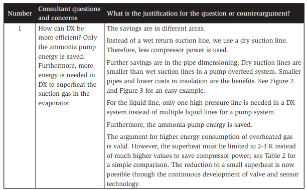
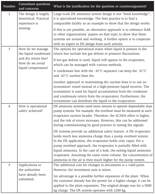
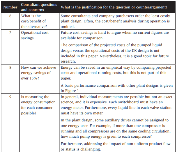
In the end, a growing body of literature and experts from the IIAR community provided examples of plants that operate comparably. This support helped convince the client to order a DX system.
General Conditions of the Tender
Refrigerant ammonia was set as the charge from the beginning of the project. Furthermore, we needed to use the heat recovery from the refrigeration plant for the under-floor heating and a third-party air curtain application. The tender was designed to avoid a secondary refrigerant system for the air coolers. The refrigeration equipment needed to be centralized in one engine room. In addition, we followed regulations regarding the building code, building permit, and requirements from the Federal Emissions Protection Act. The piping and valve stations were planned on the roof to avoid ammonia contaminating workspaces during leaks.
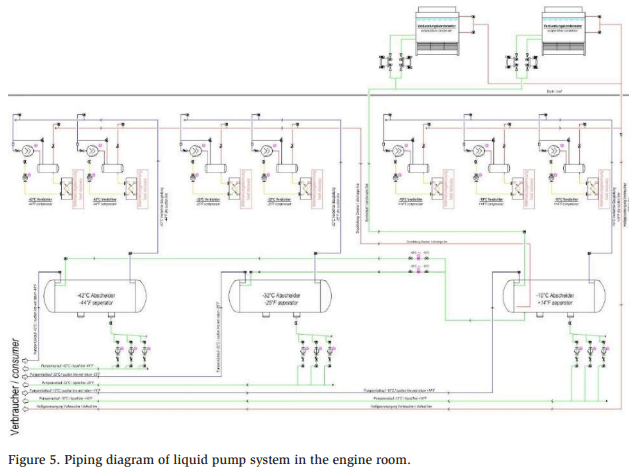
Layout
Figure 2 shows the layout of the facility. Generally, three temperature stages are present, as detailed in Table 2. The control cabinet room is the only room not operating by ammonia because of the risk of the reaction of copper and ammonia in case of leakage. The cold stores, cold store docks, chilled area, and chilled area docks are equipped with two ceiling-mounted air coolers. The engine room and switchboard cabinet room have one ceiling-mounted air cooler each. The chilled work areas each include one double-coil air cooler. In addition, one small blast freeze has one ceilingmounted air cooler. Two larger blast freezers employ two ceiling-mounted air coolers each.
Furthermore, the tender required heat recovery in the plant. Heat recovery is used for under-floor heating in deep frozen spaces, also providing warm glycol for a thirdparty air barrier system. In the case of excessive heat or a malfunction of the thirdparty glycol system, an emergency cooler is on the roof to achieve the operational safety of the refrigeration plant.
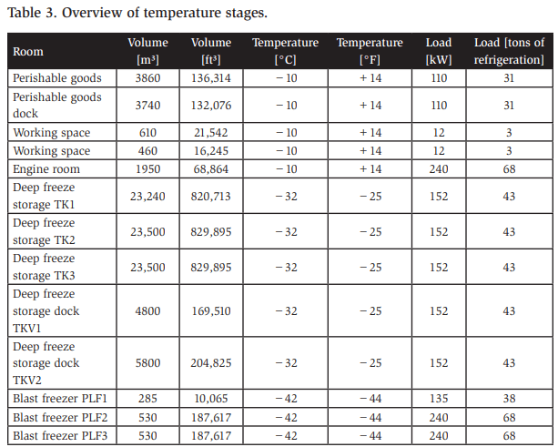
The associated loads can be classified into three suction temperature categories as follows:
- −42°C [−44°F] blast freezing
- −32°C [−25°F] cold storage and docks
- −10°C [+14°F] Food picking, docks, and engine room
Differences in System Design
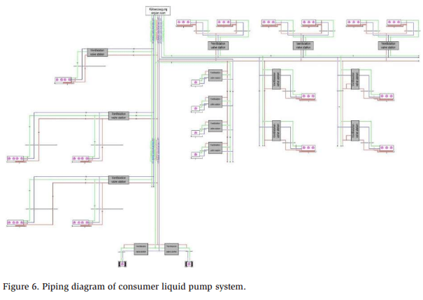
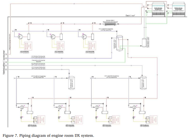
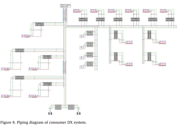
Figures 3 and 4 give a detailed overview of the pump system design. The DX system design is shown in Figures 5 and 6.
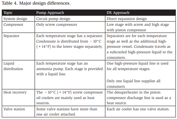
Table 3 lists the major design differences in the system designs. The DX system has the significant benefit of energy efficiency and operational cost savings. The drawback is the higher installation cost. Savings can be achieved with fewer and smaller pipes, smaller separators, and a piston instead of a screw compressor. However, costs rise with the number of valve stations, number of sensors, wiring and programming complexity, and larger and more expensive evaporators. In this case, the DX design is approximately 15% more expensive than the standard pump design.
Obstacles in Plant Design
DX plant design has been applied in the IIAR community for many years. DX system design introduces several issues that need to be addressed. The following discussion shows an overview of the most critical ones.
Dimensioning Separator
The most vital decision is regarding the designs of the separators, pump, and DX system. The system must be able to collect all the refrigerant charge in one or all separators during plant modification or in case of emergency. The condensate from defrost must be separated before the suction gas arrives at the compressors. Furthermore, liquid accumulating over an extended shutdown period must be managed. Some valuable insights into separator design are provided in the literature (Wiencke, 2002).
Pressure Control
For a DX system, a constant discharge pressure is crucial to achieving a proper liquid feed to the higher-temperature evaporators. In addition, a constant discharge pressure in combination with subcooled liquid prevents flash gas in liquid supply lines.
Furthermore, the suction pressure for the return line should be constant. Pressure fluctuations can cause condensation in the dry return line.
Oil Management
In a pump overfeed system, separating the excessive oil from the compressor in the separators is common. The oil thrown from the compressor in a DX system needs to be removed before entering the evaporator. The oil in the evaporator reduces the performance because of the reduction of transfer surface area due to oil contamination. Different approaches are available, for example, a large oil separator on the compressor unit or an additional oil separator in the discharge line. The difficulty is the state of oil in the discharge line, which has a much higher viscosity, often referred to as “angel hair.” Therefore, the oil from the discharge gas is much harder to remove than from the liquid phase in a separator.
Purger Connection
Depending on the chosen system, some measurements are required. In this project, a self-built automatic purger was chosen. A purger should be considered for both systems. The mixture of ammonia and non-condensable gases runs through a pipe in a heat exchanger. The ammonia condensate and non-condensable gases accumulate in the heat exchanger. The non-condensable gases are purged from the heat exchanger to the ambient air through a solenoid valve, and the ammonia condensate is returned to the plant. The issue with this system is that the subcooled highpressure liquid comes from the highest-pressure level. The first design discharges the ammonia condensate to the -32°C [-25°F] separator, which may cause refrigerant misplacement when too much high-pressure liquid is transferred to the -32°C [-25°F] separator.
Evaporator Design
Choosing the right design is essential, and the following points should be considered:
Regarding the materials used, stainless steel has a much lower thermal conductivity than aluminum. Therefore, the design is different. Twisted sheet metal for a turbulent refrigerant flow or, in general, more surface area can enhance the tube surface.
Hot gas defrost condensate removal is vital to avoid liquid compression in the compressor. A separate condensate line can be used. In addition, water or electronic defrost can be installed next to a separator before the compressor.
The literature (Jensen , 2006) states that because of the high density change from liquid to vapor and the high thermal conductivity, ammonia DX evaporators are difficult to design. However, sufficient and well-known evaporator suppliers are available to support DX evaporator design.
Liquid Feed Control to Evaporator
The evaporator has different stages of operation, e.g., cooling, defrosting, stopping, and running. Each operational stage has different demands for liquid control, and sensors can serve these requirements. These sensors can be for temperature, pressure, moisture, or a mix. Furthermore, the placement of the sensors is important. A long delay in the sensor measurement, processing time, and change in liquid feed can lead to flooding of the evaporator coil.
Defrost and Liquid Management
In this project, an ammonia hot gas defrost is selected. During the defrost, a phase change from gas to liquid ammonia occurs. Before restarting the cooling process, all the liquid must be drained out of the evaporator—similarly for ammonia gas that condensates in cold surroundings, such as cold storerooms, if an air cooler does not operate for a long period. Both liquids must be addressed.
Heat Recovery
In this project, the heat recovery requirement is not excessive. If piston compressors are chosen for different reasons on the high stage, a limited amount of heat recovery is available from the discharge gas compared to the oil-cooling energy from a screw compressor, assuming the same requirement for heat recovery temperature level. Typically, this is a 65/50°C (149/122°F) glycol circuit. If the discharged gas must be condensed in a heat exchanger for heat recovery purposes in the piston during winter, the pressure must be built up to achieve the desired temperature. This negatively affects efficiency, owing to the high condenser pressure during winter operation.
Lessons Learned After Two Years of Operation
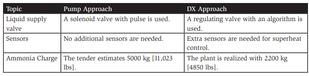
Comparing the performance of different plant designs is challenging. Various factors have significant impacts, including climate area, the type and turnover of the product, building type, the level of building insulation, and the education level of onsite employees. Each of these factors influences plant performance. For comparison, Jenson (2022) published a paper showing different plant designs in perspective. The author referenced the designs using the specific energy coefficient (SEC).
Another plant in the same area is operated by the same company. The design is a centralized ammonia pump overfeed system. Despite the difference in plant size, the product type and flow are similar. The other plant operates with an SEC of 47 kWh/ m³/yr, 24% more energy consumption than the plant under study, which has an SEC of 36 kWh/m³/yr (based on live plant data).
Figure 1 shows this overview of Jensen (2022), the DX plant, and the other ammonia pump plant. The DX design is shown in red, and the pump system is shown in blue.
A logistics company operates the plant. Therefore, various products and packaging from the company’s customers come through the plant. As a result, comparing performance figures is difficult since it depends largely on the product. For example, warm bread that goes directly to a cold store results in high energy consumption compared to a pre-frozen product. Furthermore, turnover is another factor. Daily warm-product deliveries yield higher energy consumption than weekly deliveries.
During commissioning, excessive air in the system was present, leading to refrigerant displacement from the high-pressure liquid separator into the −32°C [−25°F] separator. As a result, the liquid needed to be purged from the separator again. An automatic purger can reduce commissioning problems.
For the service department, the most common errors were faulty liquid supply valves on the valve stations. Furthermore, we experienced leakage in the service screwing of valve blocks.
The maintenance experience was positive. No design changes were needed, and we did not experience failures of liquid feed valves to the evaporator. Failures of which the customer was aware include the aforementioned air purger issue and four broken evaporator fans. Furthermore, maintenance efforts and energy costs for the ammonia pumps were saved with this system design. Unfortunately, further testing, such as set point changes for seasonal adjustment, was not possible.
The initial planned investment cost for the liquid overfeed pump system was 7% lower than the actual build cost of the DX system. The liquid pump system had less evaporator cost because of the lower surface area and fewer sensor requirements. In addition, the DX system uses a desuperheater for heat recovery, where the pump system can use the oil for heat recovery. The pump system was designed without a high-pressure receiver. The DX system is more cost-efficient, owing to separator size, smaller dry suction lines, fewer liquid supply lines, and no ammonia pump requirement. However, this conclusion is not universal. Several hours were spent on this project in design and clarification during construction. Another plant in a similar design is expected to cost the same as or slightly more expensive than a liquid overfeed pump system.
Conclusion
The DX system was shown to be an energy-efficient and low-charge refrigeration plant design. DX is a good solution not only in a decentralized or single-temperature level approach but also in a centralized multistage approach. Still, the primary task is to inform and convince relevant companies that DX is available and manageable. Interestingly, some systems are called ammonia DX systems, but they still use NH3 pumps for liquid management.
When the major points in this paper are addressed, we can design a reliable and efficient plant that provides operators with a significant operational cost advantage.
Furthermore, the trend is heading toward an energy leasing model in Germany. In this model, large energy suppliers offer to build and operate refrigeration plants for companies. The company then leases the refrigeration and pays for what it uses, similar to an electricity bill. Energy suppliers have the potential to become valuable players in the drive to change the industry to more efficient plant designs.
References
Jensen SS. (2006). Technical Paper #5 Direct Expansion Feed in Dual Stage Ammonia Plants: Operating Experiences in a Large Refrigerated Distribution Center. Reno, NV, 2006 Ammonia Refrigeration Conference & Exhibition.
Jensen SS. (2022). Liquid Overfeed Ammonia Refrigerating Plant and Energy Efficiency. Savannah, Ga., 2022 IIAR Natural Refrigeration Conference.
Wiencke B. (2002). Sizing and Design of Gravity Liquid seperators in Industrial Refrigeration. Kansas City, Mo.: 2002 IIAR Ammonia Refrigeration Conference.
Acknowledgments
The authors would like to acknowledge the support of all parties involved in this project who helped realize it. Special thanks go to Bruce Nelson, Bernd Löffler, and Stefan Jensen for contributing to this project. Furthermore, we appreciate all employees for their efforts in this work.
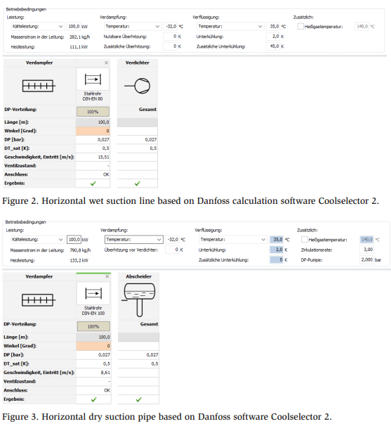
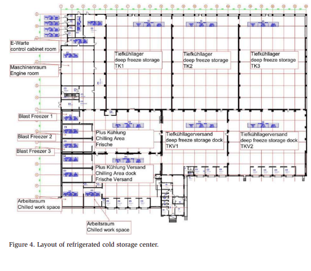
Appendix
The simple comparison of pipe sizing uses a 100 m horizontal suction line. The line should not exceed a pressure loss of over 0.5 bar. Other values, such as cooling capacity and evaporation temperature, are the same. In conclusion, the size of the dry suction line is one size lower than that of the wet suction line. In addition to the pipe sizing, the insulation cost is less.