Technical Paper #2
Performance Analysis of CO2 Heat Pump Modes for Refrigeration Systems: A Case Study
Author: William Slope, Refrigeration Sales Engineer Air Treatment Corporation, Frédérick Lavallée-Trubiano, Director of Engineering M&M Carnot
Abstract
Transcritical CO2 heat pumps are emerging as a viable alternative to synthetic air- or water-source heat pumps, and they present an opportunity for electrification while eliminating the need for refrigerants with high global warming potential. The purpose of this technical paper is to assess the coefficient of performance for CO2 heat pumps using varying water return temperatures. The water return temperature (coming back to the heat pump) impacts the maximum possible supply temperature (going out to the process). The return temperature also determines the percentage of heat available for reclaim, based on the properties of CO2 in subcritical and transcritical operations. Herein, a theoretical maximum efficiency is discussed and compared to the actual operating efficiency of an installed system. The installed system has a constant saturated suction temperature, with variable discharge pressures and ambient conditions. This paper concludes with design recommendations according to the findings.
Introduction
With multiple transcritical CO2 compressors on the market, compressor data has become readily available. This paper uses this published data to examine the effects of water return temperature on a heat pump’s coefficient of performance (COP). Most transcritical CO2 systems on the market are currently used for cooling loads with heat reclaim, as is the case with the example system in Montreal, QC. Although it is feasible to create a heating-only heat pump with an air-source outdoor evaporator, in this paper, most of the discussion and analysis centers around simultaneous heating and cooling loads.
CO2 to Water Heat Pump Efficiency
Maximum Efficiency of CO2 to Water Heat Pumps Based on Published Compressor Data
In this section, we discuss the heating COP of CO2 heat pumps based on compressor data published by the manufacturer. A computer program was built to query manufacturer data and calculate COPs for various conditions. COP is defined as the amount of energy produced divided by the energy used. Two different scenarios were investigated: single-stage (Figure 1) and two-stage (Figure 2) refrigeration systems. Various suction temperatures and gas cooler outlet temperatures were used in both scenarios to determine the range of COPs. Table 1 lists the conditions used for singlestage system operation. Each data point was obtained with 20°F of useful superheat.
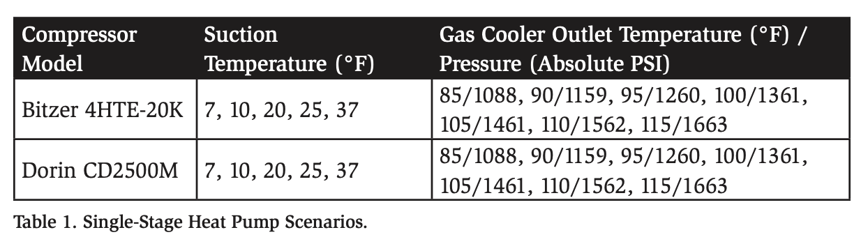
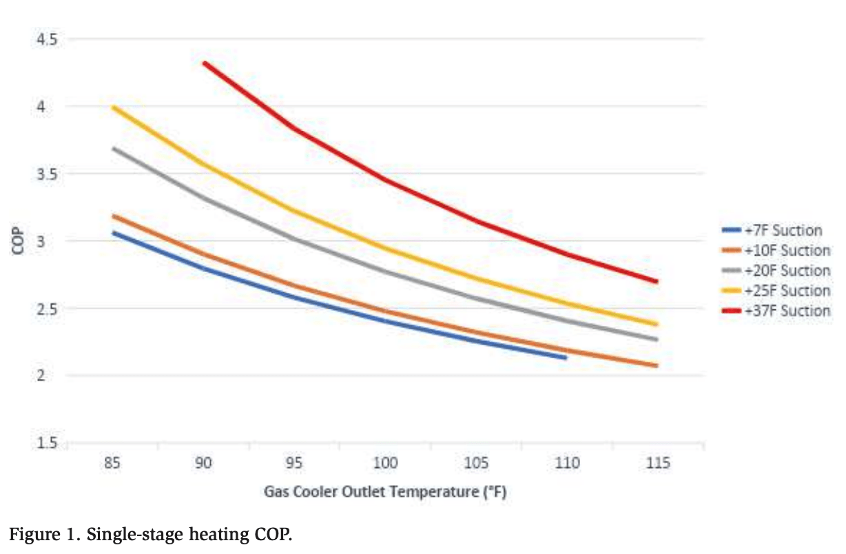
The missing data in Figure 1 at 7°F suction and 85°F gas cooler outlet, and 37°F suction and 115°F gas cooler outlet is due to the limited compressor operating envelope. Although different compressors were examined, there was no significant difference between COPs. The selected compressors, shown in Tables 1 and 2, represent examples of compressors that are frequently used in CO2 systems.
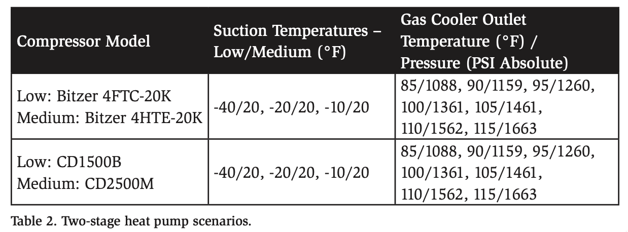
Two-stage refrigeration systems were analyzed using the same computer program (Figure 2). For this set of data, the power required by the medium-temperature compressor was automatically adjusted to match the low-temperature heat of rejection using the following formula:
Medium-temperature compressor power (kW) = Low-temperature heat rejection
(BTU/hr) * Medium-temperature compressor efficiency (kW/(BTU/hr))
The total required power was determined using the sum of the required lowtemperature and medium-temperature compressor power.
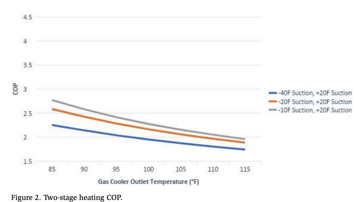
As both cases (single- and two-stage heating) show, the heating COP increases as the gas cooler outlet temperature decreases, as long as 100% of the heat is rejected into the water loop. This correlation is due to the lower compressor discharge pressures required at lower gas cooler outlet temperatures. In other words, less work is required by the compressors to provide lower temperatures. Reaching the desired water temperature in the heating loop using the lowest possible gas cooler outlet design (85°F, or lower in the case of subcritical operation) would be most efficient.
Efficiency of an Operating CO2 to Water Heat Pump
In this section, we consider an actual refrigeration system that is designed to maximize its efficiency by moving the heat from a cold room to a warm glycol loop. The glycol loop is used to heat different locations in the building, such as the general sales area, front door air curtain, office, and back store. The design criteria of the system are listed as follows:
Location: Montreal QC, Canada, IGA Beaumont
Cooling load: 168 kBTU/hr @ −25°F (−31.7°C), 1002 kBTU/hr @ +20°F (−6.7°C)
Air-cooled gas cooler design for 97.7°F (36.5°C) gas cooler outlet
Glycol 85°F (29.4°C) inlet temp, 110°F (43.3°C) outlet temperature, design heating capacity 1066 kBTU/hr
The primary purpose of the system is cooling, and heating is secondary, performing backup heating in case the cooling load is lower than the required heating load. Typically, a system installed in the Montreal region operates with the lowest pressure possible, based on the outdoor temperature, to increase the refrigeration COP. As shown in the following section (Tables 3–8), reducing the pressure/condensing temperature reduces the percentage of possible heat reclaim at high temperatures. Based on the glycol inlet temperature of 85°F (29.4°C), the system should maintain a discharge pressure of 1159 PSIA, which corresponds to 90°F (32.2°C) for themaximum COP, to transfer 100% of the cooling load in the glycol loop. If transferring 100% of the heat from the refrigeration system is not required, the system can take advantage of the outdoor temperature to subcool the CO2 below 90°F (32.2°C ), which increases the system COP without impacting the capacity to produce valuable heat.
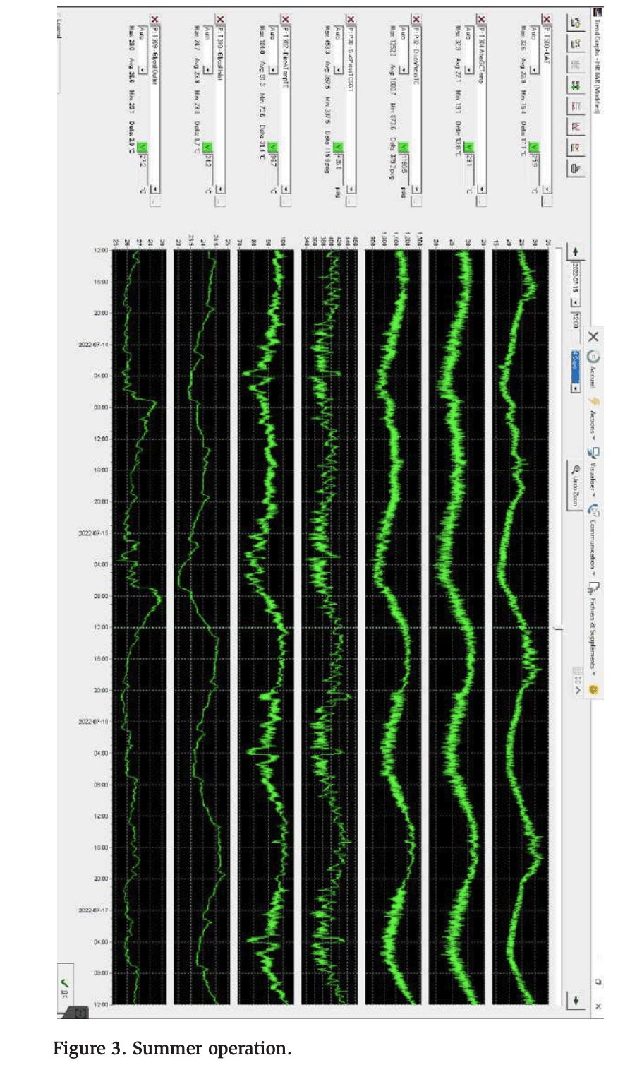
Four days of data points were extracted at different times of the year to examine the system operation. The first data set, Figure 3, shows the operation during the summer season. The data show that the heat reclaim is rarely active since the average outdoor temperature is above 70°F (21.1°C); thus, almost no heating is required. For this reason, the discharge pressure follows the outdoor temperature to maximize the efficiency of the refrigeration system. The heating load is low and is only used for dehumidification, so the required glycol temperature is lower.
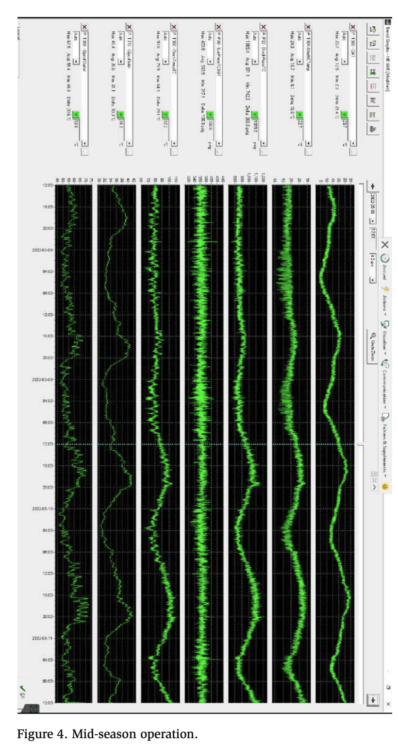
The second set of data, Figure 4, shows a different operating condition. The average outside temperature is approximately 53°F (11.7°C), including temperatures from 35 to 77°F (1.7 to 25°C). The required heating load is higher than that during the summer season, and the glycol temperature supplied by the system is maintained at approximately 125°F (51.7°C) with a return of 95°F (35°C). To maintain the heating load, the system can discharge an average pressure of 871 PSI, which corresponds to a condensing temperature of 73°F (22.8°C), and exploit some subcooling at the gas cooler, because the average gas cooler return temperature is 65°F (18.3°C). Subcooling the refrigerant at the gas cooler increases the refrigeration system efficiency, and by simply maintaining a constant discharge pressure, the system can reclaim a considerable amount of heat in the glycol loop. The impact of subcooling on the heating and refrigeration COPs is discussed in more detail in the next section.
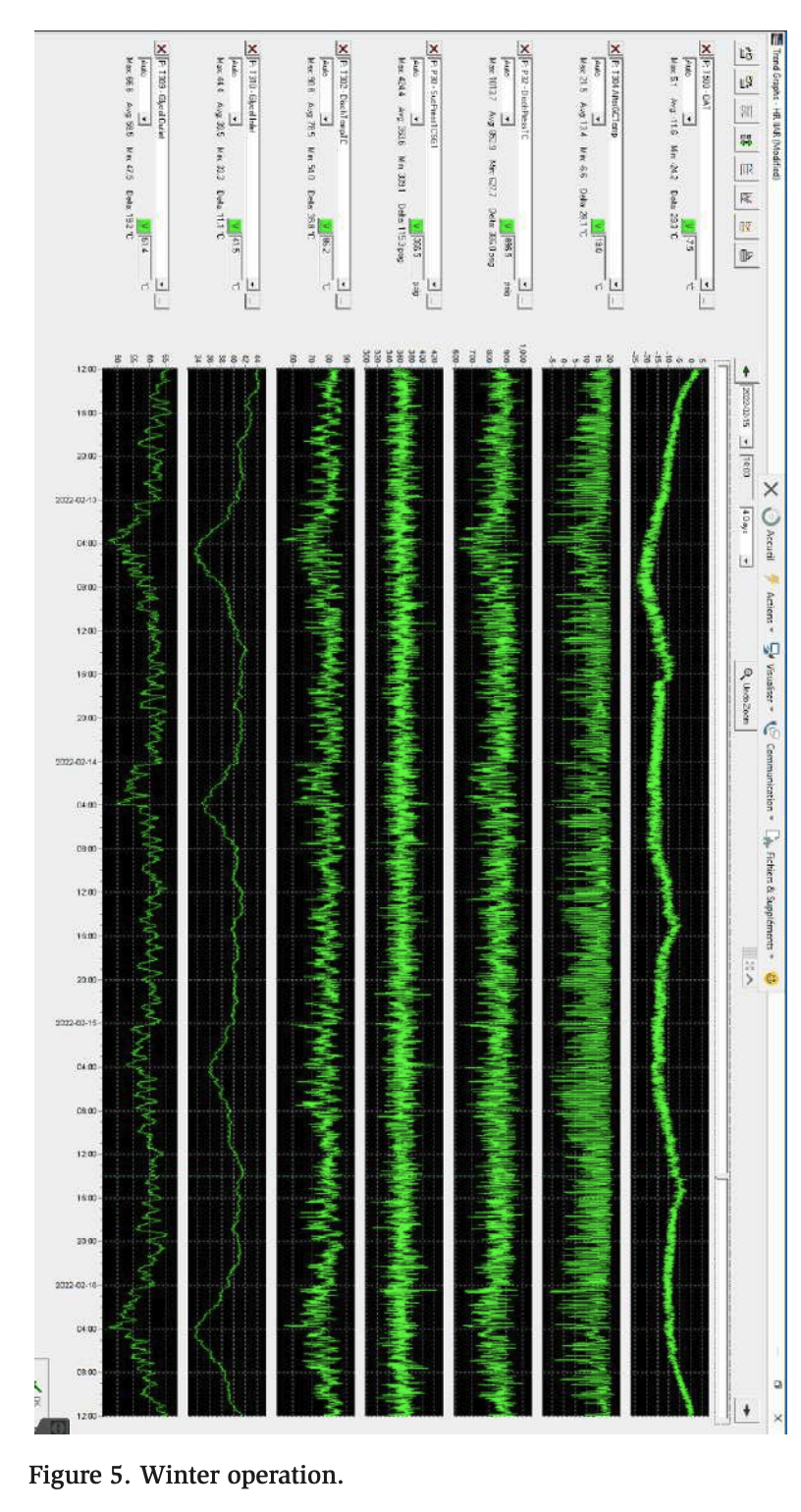
The third set of data, Figure 5, represents winter operation, with temperatures ranging from −11 to 41°F (−23.9 to 5°C). Under these ambient conditions, the system can operate at a constant pressure of 750 PSI to maximize the refrigeration efficiency, but it minimizes the amount of heat reclaim. Only about 15% of the heat can be used because the glycol being heated is coming in at an average temperature of 90°F (32.2°C). To increase the heating capacity, the discharge pressure is increased to 850 PSI. This increases the available heat for heating from 15% to approximately 21%. This is a 40% increase in heating capacity, with a small impact on refrigeration efficiency. The increase in discharge pressure allows the system to heat the glycol to 140°F (60°C), as shown in Tables 4 and 6 (using the midpoint between 80 and 100°F [26.7 and 37.8°C] for the water entering the pump), and the third data set shows the same behavior at an average temperature of 140°F (60°C). The COP of this additional heating is approximately 2.78 when we calculate the reclaimed energy divided by the additional energy used for the cooling at a higher pressure.
Heating Process and Gas Cooler Outlet Temperature Selection
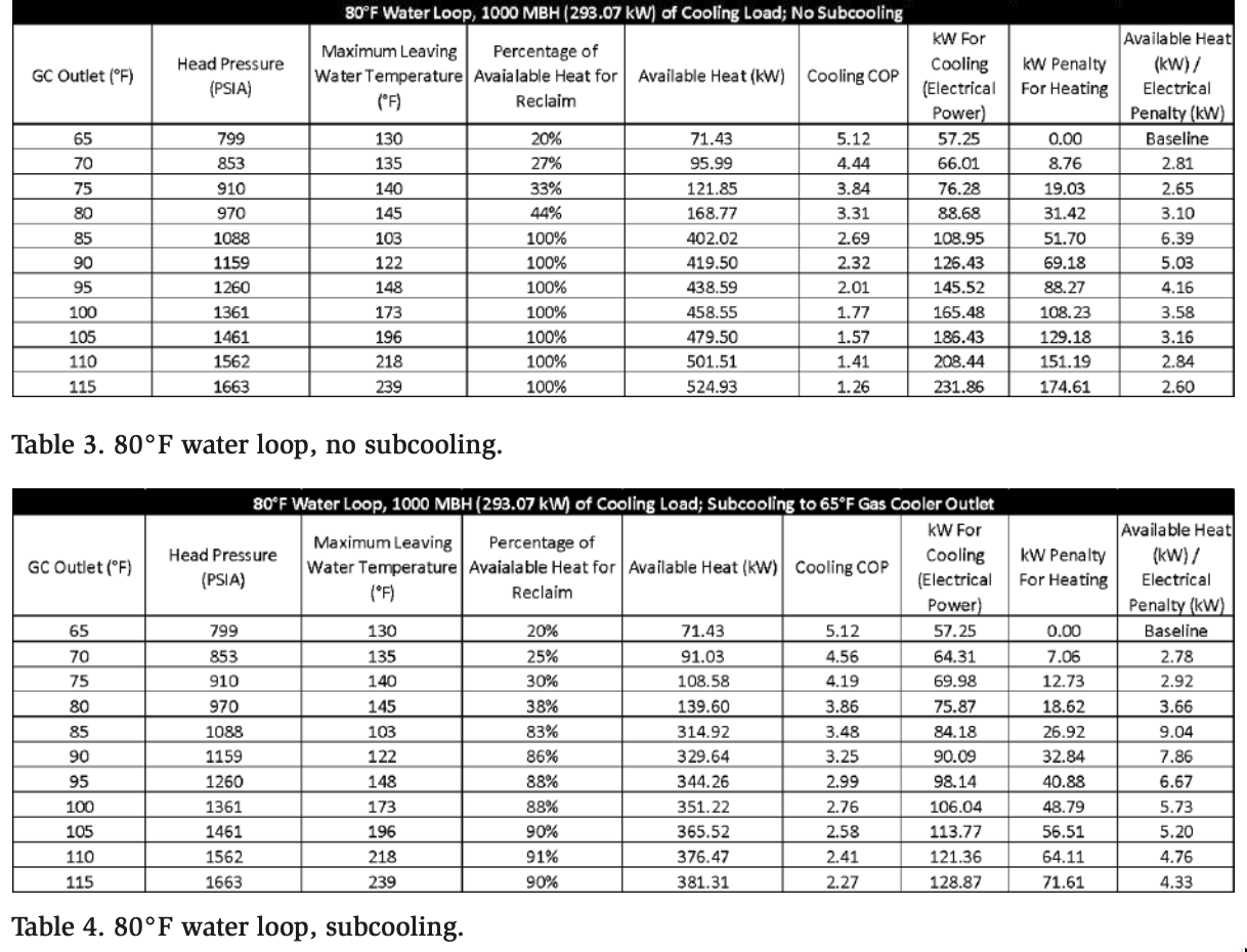
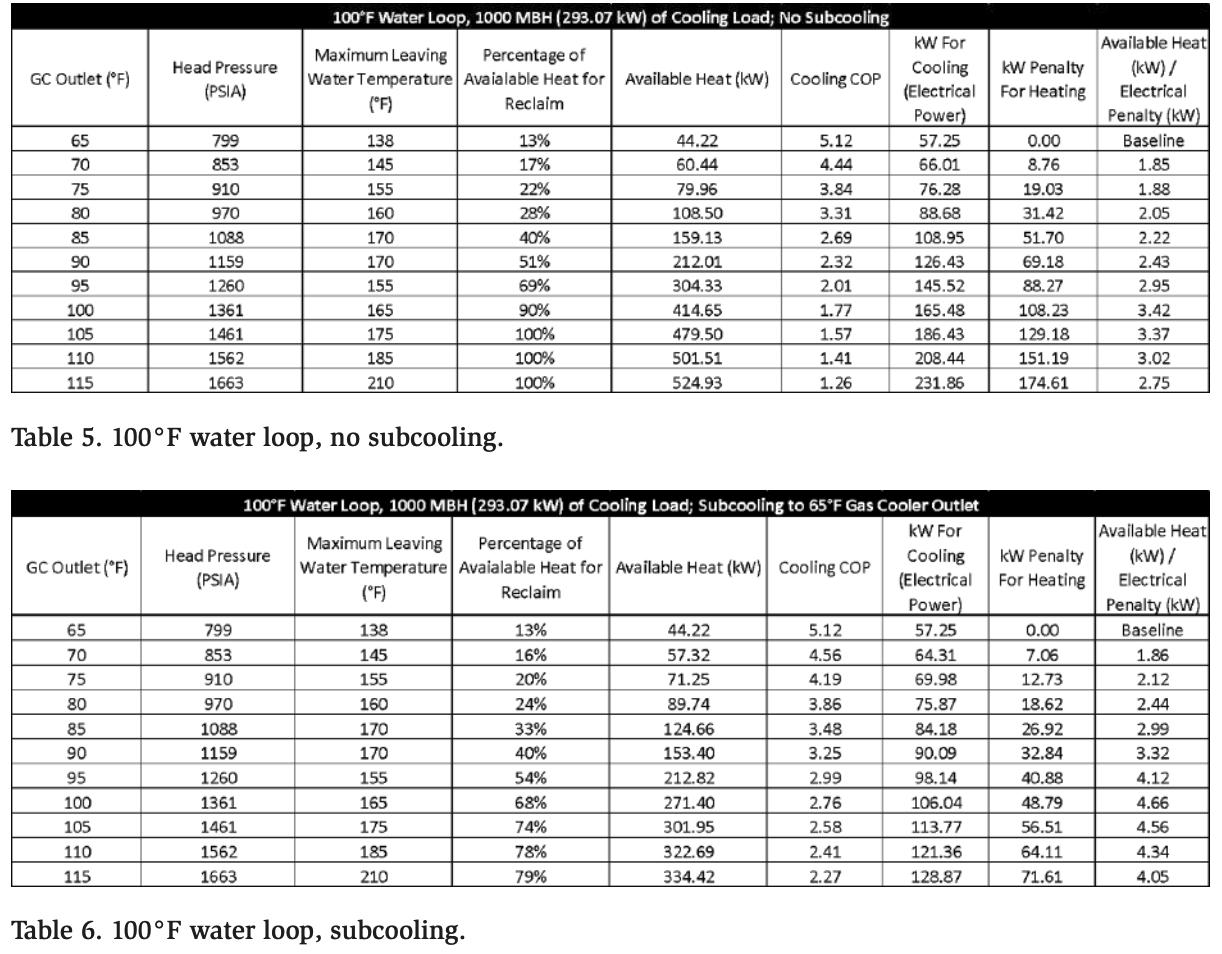
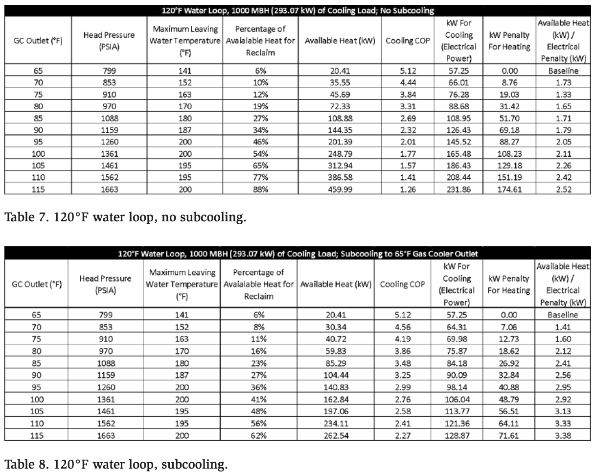
In this section, we present calculations of an example using 20°F for the saturated suction temperature, with varying outlet gas cooler temperatures. Each calculation uses a set return water loop temperature to assess the heating and cooling COPs. The results for different return temperatures are compiled in separate tables and serve as a guide to recommended operating parameters that maximize efficiency based on project requirements. The tables also present the COP-based advantages of subcooling.
Another metric must be introduced: available heat (kW)/electrical penalty (kW). This metric is based on the increase in electrical power (kW) and resulting heat (kW) compared with a baseline using 65°F for the gas cooler outlet. The value represents a dimensionless coefficient that is useful for determining how efficiently additional heat can be obtained to satisfy a heating load when the cooling load is constant.
If possible, it is advantageous to reduce the return loop water temperature. This is due to the enthalpy properties of CO2 at elevated return temperatures. A lower percentage of the total enthalpy becomes available when the return water temperature increases. Not only must the discharge pressure increase, but the available heat ratio drops simultaneously, as illustrated in Figure 6.
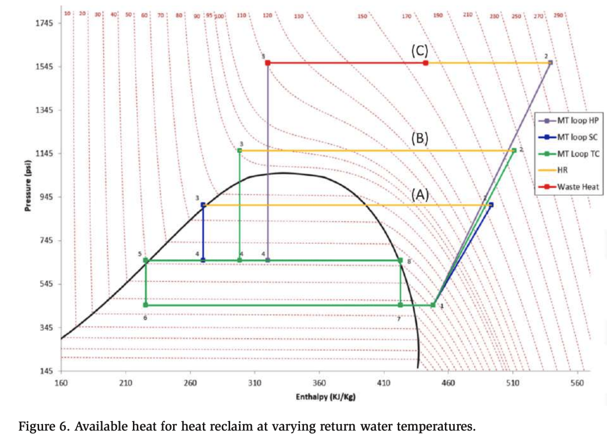
In Figure 6, the compressor discharge at (A) represents a direct CO2 to air heat exchange at 75°F. Furthermore, (B) represents CO2 to water heat exchange at a return water temperature of 90°F. Finally, (C) represents CO2 to water heat exchange at a return water temperature of 160°F. Heat is wasted at higher return water temperatures and requires higher energy input.
Scenario 1: 80°F Water Return Loop, +20°F Saturated Suction, 1000 MBH (293 kW) of Cooling Load
Scenario 2: 100°F Water Return Loop, +20°F Saturated Suction, 1000 MBH (293 kW) of Cooling Load
Scenario 3: 120°F Water Return Loop, +20°F Saturated Suction, 1000 MBH (293 kW) of Cooling Load
Additional Considerations and Discussion
Notably, it is necessary to clarify the requirements of the heat pumps before construction of the project begins. Many different types of buildings use CO2 heat pumps, such as food and beverage processing facilities, freezer/cooler storage, commercial office buildings, etc. Each of these systems likely has different temperature and load requirements. For actual refrigeration loads, the saturated suction temperature should be used. Once a suction temperature is established, a target water temperature can be set. As we discussed in the previous section, lower return water temperatures enable a larger percentage of heat reclaim to be transferred.
Lower return water temperatures can be achieved by designing a heating system with a large temperature difference. In addition to taking advantage of the greater heating capability from the CO2, the pumping energy would also be decreased as a result of the decrease in total water flow. Another strategy to reduce overall energy consumption is to install a buffer or storage water tanks. This allows for more efficient and stable operation, as opposed to constantly responding to load variations by increasing head pressure.
Using the data from Tables 3–8, we can create improved control logic to maximize system COP. By understanding the electrical penalty for elevating head pressure in relation to the increase in obtained heat, we can make specific decisions for each system and operating environment. Often, it is advantageous to slightly increase head pressure for large increases in available heat. A dimensionless coefficient, or another metric, can be helpful to quantify this relationship, as used in this study.
Some other areas of consideration are listed below. All of these factors should be assessed when designing and selecting equipment and are worthy of further study.
- Control strategy to optimize COP
- System design for all operating conditions
- Standstill and system restart
- Higher design pressure needed for higher temperatures
- Standard building heating systems not designed for a larger temperature difference and lower temperature return
- Design coordination with all parties from the start
- Whether or not to include backup heat generation or rely on driving up head pressure at an energy penalty
Conclusion
Utilizing compressor data from transcritical CO2 compressor manufacturers, we calculated heating and cooling COPs. A computer program was created to query the compressor data under various conditions. The results were assessed using comparative metrics that demonstrate the tradeoffs associated with the heating process loop temperatures. We can conclude that a) raising saturated suction pressure increases heating COP, b) lower return water temperatures to the heat pump increase heating COPs, c) the percentage of heat available for reclaim is a function of discharge pressure and return water temperature because of enthalpy, and d) when you have a cooling load, it is often advantageous to elevate discharge pressure to meet the heating load and achieve desirable COPs.
References
AHRI. (2022). Standard for Performance Rating of Commercial and Industrial Unitary Air-conditioning and Heat Pump Equipment (2022)
Bitzer Software v6.17.8 rev2725
Dorin Software 21.10
Emerson Product Selection Software Version 1.1.5.0
MT Alliance v8.5.0.1055
Acknowledgments
Groupe IGA Beaumont
Tommy Dolbec, Ing., VP Engineering | M&M
Carnot Carnot Refrigeration
Air Treatment Corporation