Technical Paper #12
Interior Ammonia Release: Dispersion, Ventilation, and Hazardous Zone of the Negligible Extent Volume
Author: William J. Greulich, Principal, Kensington Consulting
Abstract
Currently, ANSI/IIAR 2 Standard for Design of Safe Closed-Circuit Ammonia Refrigeration Systems (IIAR 2021) requires machinery room emergency mechanical ventilation systems to provide no less than 30 air changes per hour based on the gross machinery room volume. When this emergency ventilation rate is in place, the National Electrical Code (NFPA 2023), adopted by reference IIAR2, allows for an “adequate ventilation” exemption for spaces under the electrical hazardous area classification. The IIAR standard also requires de-energization of specified electrical equipment in the room when ammonia is detected at 40,000 ppm, ¼ of the lower flammable limit (LFL). This study presents an overview (with calculations) of a simple integral dispersion model applied to the identification of a potential gas volume resulting from the release of anhydrous ammonia (R-717) deemed so small that significant injury or damage is not expected from ignition, referred to as a volume of negligible extent, Vz. The study also examines issues of ventilation and accidental release theory to elucidate the larger picture of indoor ammonia refrigeration system releases. This work is intended to support the development of global safety standards and safe, practical design solutions by presenting assessment results for ammonia release jet flammable volume extents and rates, as well as the associated adequate mechanical ventilation rates for several room mixing efficiencies, to limit room background concentrations to ¼ LFL. These results may assist in re-evaluating current requirements and offer a potential requirement format that comprehensively considers the specifics of ammonia and the size of machinery rooms.
Ideal room release and ventilation formulation
Consider a room of volume V0 (m3 ) containing a constant ammonia gas release at rate qs (m3 /s) and a constant mechanical ventilation volume outflow rate q1. Room ammonia mass balance leads to the following ordinary differential equation (ODE): (Brighton 1989) (Webber 2011)
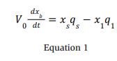
Here, xb, xs , and x1 are the ammonia volume fractions (m3 /m3 ) of the room background, release, and ventilation outlet, respectively. Furthermore, conservation of the room volume at constant pressure requires q1 = qs + q0.
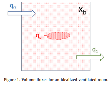
In practice, real rooms are not ideally mixed owing to dead space(s), physical obstructions, or general inefficiencies in the ventilation flow patterns relative to the release location and geometry. These non-idealities may be broadly addressed by introducing a dimensionless room background mixing efficiency, ε, which is typically less than unity:
![]()
With:
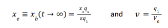
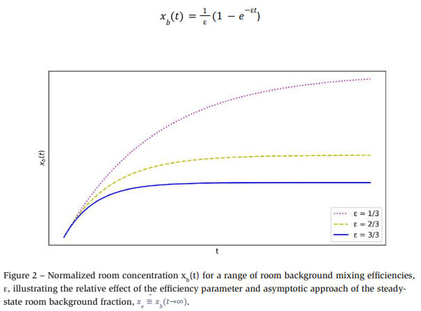
Figure 2 shows the results obtained for a normalized (xe = 1/ε, v = 1) form of the mixing equation solution to illustrate the relative effect that a range of room background mixing efficiencies has on the time required to asymptotically approach the steady-state room background concentration.
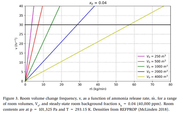
Additionally, Figure 3 illustrates the volume change frequency, v (hr-1), required to achieve a steady-state room fraction of xb = 0.04 (40,000 ppm, ¼ LFL) as a function of the constant gas mass release rate, m. (kg/s), for a range of room volumes, V0. Often, real refrigeration system ammonia gas release source terms are more complex for releases with a condensing liquid fraction that may pool and subsequently vaporize at a varying rate. The all-gas simplification is used in an ideally mixed room to illustrate the relationship between gas mass flow and ventilation volume discharge rates required to maintain the ammonia room background fraction below the IIAR-2 required detection and de-energization limit of 0.04.
Completing the background, the current IIAR-2 requirement is derived from the following: (Brown 2005)
“Maximum Probable Gas Generation/Release Rate: Industry experience recognizes that the failure or rupture of a ½” high-pressure, high-temperature liquid line (i.e., 181 psig, 95°F) is the most probable worst-case scenario. One can calculate a probable gas generation rate for a given piping configuration, accounting for pipe length, valves, and fittings, by applying accepted hydraulic formulas along with the physical properties of ammonia. (Crane Company 1965) A piping configuration of a single ½” globe valve at the main source and 100 equivalent feet of pipe between the bulk liquid source and the release point is a reasonable and appropriate design to consider. Applying the hydraulic formulas to this piping configuration, a release rate of 42.4 lbs./min can be calculated. The release of 42.4 lbs./min of 95°F liquid will produce 9.71 lbs./min of flash gas. We conservatively assume that initially, 75% of the remaining liquid flow will evaporate by heat transfer from contact with warm surfaces and the surrounding air. This boiling generates an additional 24.36 lb/min; thus, the maximum total gas generated would be 34.07 lbs.”
And,
“Thus, the total ventilation rate to maintain the gas generated from a steadystate release … at 25% of the LFL would be 19,808 cfm. This calculation shows that 20,000 cfm of ventilation is sufficient for a probable worst-case scenario.”
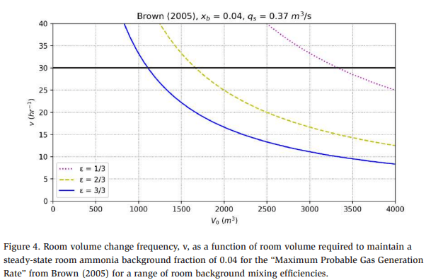
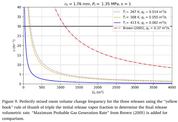
Figure 4 shows the room volume change frequency required to maintain a steadystate room ammonia background fraction of 0.04 as a function of room volume for the “Maximum Probable Gas Generation Rate” from Brown (2005), using a range of room background mixing efficiencies. For the ideally mixed room scenario, ε = 1, developed by Brown, room volumes greater than ~1100 m3 are capable of remaining below the 0.04 volume fraction (40,000 ppm, ¼ LFL) required for ventilation rates at or below 30 volume changes per hour.
Zone of negligible extent formulation
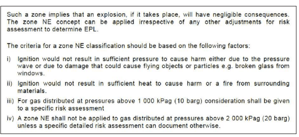
IEC 60079-10 (IEC 2020) defines a zone of negligible extent (Zone NE), Vz = 0.1 m3 , where the hazard posed by a release is deemed to be so small that significant injury or damage is not expected from ignition. (Appendix A)
Here, we adopt an approach to estimate Vz for sonic jets by considering the conservation of momentum, mass, and ammonia concentration along with submodels to estimate a release pseudo-source radius, rs (m), and dimensionless entrainment coefficient, α. (Webber 2011)
Webber (2011) proposes the following relationship:
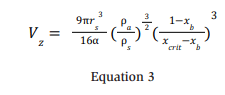
Here, ρa and ρs are the densities (kg/m3 ) of the room background and the depressurized source jet, respectively, and xcrit is the ammonia fraction of interest (i.e., volume boundary fraction for the volume of negligible extent), typically ½ the lower flammable limit (LFL). (Santon 2012)
A sonic jet results from choked flow in the release flow area when the ratio of the system to atmospheric pressures pr /pa is > B, where:
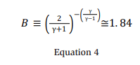
Here, γ is ~1.31 for ammonia.
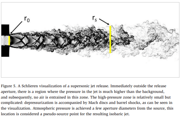
For choked flow, rs in the Vz equation (Equation 3) is not an actual hole radius but the radius of a theorized pseudo-source, which is somewhat larger, as illustrated in Figure 5. Webber (2011) notes that there are numerous estimates proposed in the literature for the ratio of physical and pseudo-leak radii, rs /r0, which is used to simplify the complex nature of the multiple shock zones seen in the Schlieren visualization (Figure 5). Webber (2011) suggests using the following “pragmatic approach” for the pseudo-source relationship.
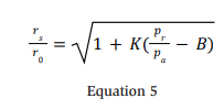
Webber attributes (Britter 1994) with the assertion that the actual release radius can be used for sub-sonic cases, and a value for the phenomenological constant, K, is given as ~0.5.
Application
A CFD simulation of the machinery room release was commissioned by the Ammonia Refrigeration Foundation, examining three ammonia release states. As a starting point for this work, the superheated gas system conditions (Tr = 413.15 K and Pr = 1.35 MPa) were chosen because they match the choked, single-phase flow conditions of the adopted model. (Davis 2022)
Figure 6 shows the combined results obtained using Equations 3–5 to calculate the (actual) flow area radius, r0, as a function of the system pressure at Tr = 413.15 K with an assumed background room ammonia volume fraction of 0.04 (40,000 ppm, ¼ LFL). For Pr = 1.35 MPa, r0 = 1.76 mm.
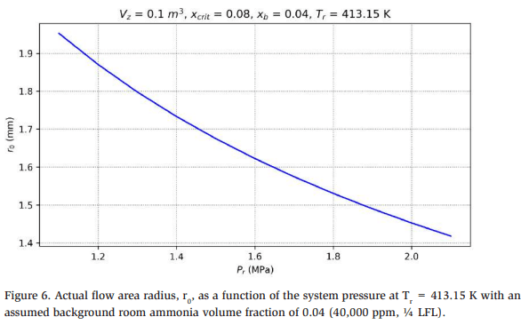
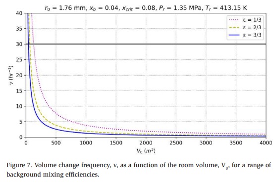
Figure 7 presents the volume change frequency as a function of the room volume for a range of background mixing efficiencies under the indicated conditions.
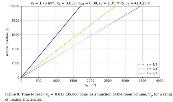
Recalling that the room fractions asymptotically approach steady state, Figure 8 presents the time required to reach xb = 0.035 (~95% of xb = 0.04) for a range of mixing efficiencies under the given conditions. The steady-state background of xb = 0.035 (35,000 ppm) is reached very slowly for all but the smallest rooms or lowest efficiencies. This suggests that using a background fraction of 0.04 for subsequent calculations is likely conservative. As a practical matter, the background fraction for the life of a release event (time before effective release mitigation) is likely much less than 0.04, indicating that Vz is also less than 0.1 m3 during this period.
The analysis is mainly focused on the choked flow, or vapor-only release, because it forms the basis of the adopted Vz calculation. Table 1 lists the initial and final parameters calculated using REFPROP and commercially available calculation and analytical modeling software, ioMosaic SuperChems®, for the three release conditions studied in the NRF-funded CFD work using the previously identified flow diameter.
Having examined the case for vapor-only release (Table 1, column 1), the flashing liquid release case is considered, as shown in Table 1, column 2. The overall flashing liquid mass release rate is almost four times larger than the vapor-only release rate. In practice, much of the released liquid fraction is aerosolized in the process and behaves as a very dense vapor. The reader is directed to the Dutch “Yellow Book” for more detailed information about this mechanism. (van den Bosch 2005) For simplicity, the rule of thumb proposed by the “Yellow Book” is applied here, stating that twice the initial vapor fraction is aerosolized and behaves as a very cold, dense vapor. The remaining mass balance is expected to pool, and the subsequent gas generation from the boiling pool is assumed to be negligible. Therefore, for the flashing case, the aerosol mass flow rate is estimated to be 0.047 kg/s.
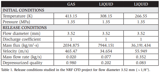
Finally, the sub-cooled liquid release is considered, as shown in Table 1, column 3. The overall release rate is almost twenty times larger than the vapor release rate shown in Table 1, column 1. Applying the “Yellow Book” rule of thumb returns an estimated aerosol mass flow rate of 0.088 kg/s. Figure 9 shows the room volume change frequency for the different release cases.
Discussion
Negligible extent volume
Figure 10 shows the laminar burning velocity, Su (cm/s), as a function of the dimensionless equivalence ratio. (Davis 2022) The equivalence ratio is the measured fuel mass-to-air mass ratio divided by the same ratio at combustion stoichiometry, commonly termed the leanness or richness of the mixture. Laminar burning velocity is a fundamental parameter describing how a planar flame propagates into a quiescent unburned mixture ahead of the flame at a specified test pressure and temperature. Furthermore, it contributes to the B2L classification of ammonia, where “B” is based on the toxicity level, “2 – lower flammability” is based on the LFL and heat of combustion, and “L” is the sub-category (of class 2) for a burning velocity of less than 10 cm/s. (ANSI/ASHRAE 2022)
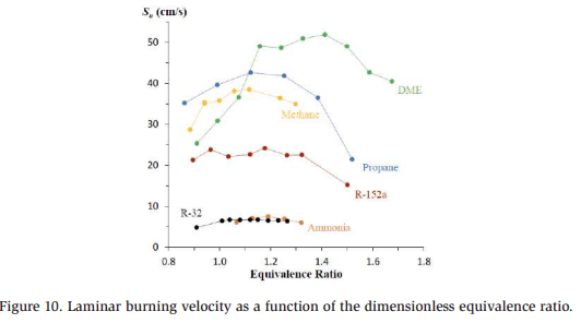
Table 2 shows the relative ignition damage potential of ammonia to other common flammable refrigerants. The exergy or thermodynamic availability indicates the maximum mechanical energy available from a material. This is the maximum amount of energy that can be transformed into an overpressure wave, the typical endpoint of ignition hazard assessments. (Crowl 1992)
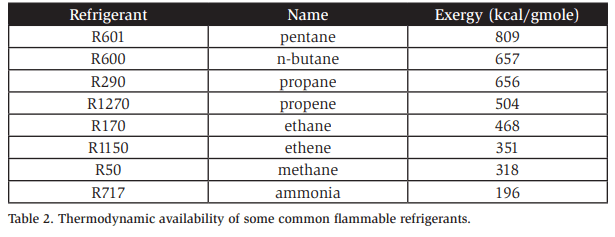
Together, the data presented in Figure 10 and Table 2 suggest that a volume of negligible extent for ammonia is safely considered to be larger than 0.1 m3 . Based on Table 2, it is reasonable to suggest a negligible extent volume of up to 0.3 m3 for ammonia. This does not necessarily mean that the release diameter should be recalculated at this volume; instead, it suggests that releases creating a volume slightly larger than 0.1 m3 are acceptable.
Release area
The negligible extent area calculation is very sensitive to the chosen flow area; therefore, determination of the suitability of the initially identified 1.76 mm (~1/16″) flow diameter is recommended.
As previously outlined, the current IIAR-2 requirement is based on the consideration of a failed ½” schedule 80 pipe with a 14 mm (~½”) internal diameter. It is important to recognize that the reported mass flow rate was significantly reduced by the inclusion of an inline valve and 100 feet of pipe between the release and the source. It is not clear if further reduction was included for the two-phase holdup or if a discharge coefficient was included. Regardless, in total, the reductions produce a mass flow rate that is less than 10% of that found by applying similar flow conditions herein, using the 14 mm flow diameter.
The UK Cold Chain Federation produced Compliance Guidance tables with an array of suggested hole size selection criteria for sealing surfaces, including fixed seals and seals moving at low and high speeds. (Cold Chain Federation 2020) Except for high-speed moving seals (compressors and pumps), the Guidance recommends flow areas of less than 2.5 mm2 (0.9 mm diameter), as found in the IEC 60079-10-1 annex B guidelines. The cold chain work also used a background mixing efficiency of 0.5 throughout.
Moreover, Colbourne (2021) analyzed leaks in propane refrigeration systems and found (with 99% confidence) that leaks will not exceed a flow area of 3.76 mm2 (1.1 mm diameter).
In closing
The first step in determining the suitability of any emergency ventilation requirement is to establish the intent of such a requirement. While normal ventilation is necessary to reject heat from machinery rooms and provide a suitable working environment, clarifying the emergency intent is crucial. If the intention is to limit the room ammonia fraction in pursuit of ignition safety, ventilation is not necessary if all room ignition sources are controlled upon detection of an ammonia room background concentration of 40,000 ppm or lower. This option of using a gas detection system coupled with de-energization as a means of protection is allowed by (NFPA 2023) and (IEC 2020).
Once the intent of the emergency ventilation requirement is understood, the main starting point for the design calculation, as outlined here, lies in the determination of the appropriate ammonia release rate, which in turn requires the determination of the ammonia conditions and release flow area. As shown in Figure 6, a conservative release diameter of roughly 3 mm was determined for the conditions examined herein. As discussed, this value is larger than those developed in the (Cold Chain Federation 2020) and (Colbourne 2021) work. However, these values are all substantially smaller than the value determined by (Brown 2005). Finalization of the release area should be based on identifying a statistically relevant failure size, derived from industry-specific experience that meets acceptable risk criteria.
Finally, it is useful to note that the curves in Figure 7 have the following form:
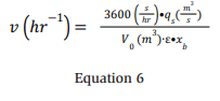
The form of Equation 6 may lend itself to general industry use. To implement this, a designer only needs to know the desired room background fraction, which is widely accepted at ¼ LFL if ignition safety is the goal, the readily available room volume, an estimate of the room background mixing efficiency, and an estimate of the ammonia volumetric release rate, which is the most critical factor. As previously discussed, it is necessary to set the release rate based on regulations, the acceptable release area volume, industry experience, and negligible extent considerations.
Appendix A
The IEC 60079-10 (2020) negligible extent definition.
Works cited
ANSI/ASHRAE. 2022. ANSI/ASHRAE 34-2022, Designation and Safety Classification of Refrigerants,. Peachtree Corners, GA: American Society of Heating, Refrigerating and Air-Conditioning Engineers.
Brighton, P. W. M. 1989. Continuous Chlorine Releases Inside Buildings: Concentrations on Emission to Atmosphere. SRD R 468, London: United Kingdom Atomic Energy Authority Safety and Reliability Directorate.
Britter, E. R. 1994. Dispersion of two-phase flashing releases – FLADIS field experiment. FM 89/2, Cambridge Environmental Research Consultants report to the Commission of the European Communities DG XIII.
Brown, R. 2005. “Machinery Room Ventilation for Industrial Refrigeration Systems: A Rational Engineering Analysis.” IIAR Ammonia Refrigeration Conference & Exhibition. Acapulco, Mexico: International Institute of Ammonia Refrigeration, Alexandria, VA.
Colbourne, D., Pitarch Mocholi, M., Munzinger, P., Oppelt, D., Paetzold, B., Vince, I. 2021. “Leak hole sizes from refrigeration, air conditioning and heat pump systems.” International Journal of Refrigeration 559 – 567.
Cold Chain Federation. 2020. Hazardous Area Classification of Ammonia Refrigeration Systems. Shinfield: Cold Chain Federation.
Crane Company. 1965. Flow of Fluids through Valves, Fittings and Pipes. Technical Paper No. 410, Stamford, CT: Crane Company.
Crowl, Daniel. 1992. “Calculating the energy of explosion using thermodynamic availability.” Journal of Loss Prevention in the Process Industries 109-118.
Davis, S., Engel, D., Pagliaro, J. 2022. “Machinery Room Ventilation and Ammonia Release Computational Fluid Dynamics (CFD) Study.” 2022 IIAR Natural Refrigeration Conference & Expo. Savannah, GA: International Institute of Ammonia Refrigeration, Alexandria, VA.
IEC. 2020. Explosive atmospheres – 60079 Part 10-1: Classification of areas – Explosive gas atmospheres. Geneva Switzerland: International Electrotechnical Commission.
IIAR. 2021. ANSI/IIAR 2 Standard for Design of Safe Closed-Circuit Ammonia Refrigeration Systems. Alexandria, VA: International Institute of All-Natural Refrigeration.
McLinden, M.O., Lemmon, E.W., Bell, I.H., Huber, M.L. 2018. NIST Standard Reference Database 23: Reference Fluid Thermodynamic and Transport PropertiesREFPROP, Version 10.0, National Institute of Standards and Technology. Gaithersburg, MD: National Institute of Standards and Technology, Standard Reference Data Program.
NFPA. 2023. National Electrical Code – NFPA 70. Quincy MA: National Fire Protection Association.
Santon, R., Ivings, M., Webber, D., Kelsey, A. 2012. New Methods for Hazardous Area Classification for Explosive Gas Atmospheres. SYMPOSIUM SERIES NO. 158 Hazards XXIII, Rugby: IChemE.
van den Bosch, C. J. H., Weterings, R. A. P. M. 2005. Methods for the calculation of physical effects – CPR 14E – “Yellow Book”. The Hague, NL: Bezoekadres Publicatiereeks Gevaarlijke Stoffen programmabureau.
Webber, D.M., Ivings, M.J., Santon, R.C. 2011. “Ventilation theory and dispersion modelling applied to hazardous area classification.” Journal of Loss Prevention in the Process Industries 612-621.