2024 Technical Paper #1
Application of a Rotary Pressure Exchanger in CO2 Refrigeration Systems
Author: Neelesh Sarawate, PhD; Azam Thatte, PhD; and Arnav Deshmukh Energy Recovery Inc., Steven Goh Vallarta Supermarkets
Abstract
Herein, the application of a rotary gas pressure exchanger (PX) for increasing the efficiency of transcritical CO2 refrigeration systems is examined. The PX uses high-pressure discharge from a condenser/gas cooler as a motive fluid to compress the low-pressure flash gas with minimal external energy input, thus reducing the power consumption of the main compressor. The PX simultaneously expands the high-pressure supercritical/liquid CO2 into a two-phase CO2 that is ready for heat absorption, thus emulating the function of a typical high-pressure expansion valve. This paper discusses multiple CO2 refrigeration system architectures using a PX, along with multiple techno-economical scenarios. Annual work savings are presented for various geographic locations with a wide range of temperature patterns in the USA. Field data from a few installations are presented, indicating that a PX can save 30% power use at temperatures of 40°C. Therefore, a PX can allow the system to run more frequently at extreme temperatures and lower the probability of shutting down the refrigeration system in a store on hot summer days or during heat waves. One PX unit can provide approximately 5.4 m3 /h or a 20% capacity increase for a typical 150 kW system.
Introduction
Carbon dioxide (CO2) refrigerant has a low global warming potential and is an attractive alternative to environmentally harmful hydrofluorocarbon-based refrigerants in commercial refrigeration applications. However, the energy efficiency of transcritical CO2 (TC-CO2) refrigeration systems generally decreases with increasing ambient temperatures. Several technologies have been proposed to increase the efficiency of TC-CO2 refrigeration systems, including expanders and ejectors [1, 2]. The application of two-phase ejectors in TC-CO2 booster refrigeration systems has recently gained attention, and multi-ejector designs with suitable control strategies have been developed to function under dynamic operation with variable loads under ambient conditions [3, 4].
In this paper, we evaluate the potential of CO2 refrigeration system architectures that employ a novel device called a rotary transcritical pressure exchanger (PX). Previous reports [5-9] have shown that the PX can simultaneously serve as a compressor and an expansion device in one compact high-speed rotary machine. Notably, the compression of low-pressure CO2 vapor in a PX is produced without external mechanical or electrical energy input, but rather, using acoustic waves in a high-speed pressure exchange between a supercritical CO2 (sCO2) fluid stream in direct contact with a low-pressure gaseous CO2. Hence, a PX can save a significant amount of compression energy in the refrigeration cycle. Furthermore, we describe a method of integrating the PX into a TC-CO2 refrigeration system to achieve high cycle efficiencies and enhance economic viability, especially in warmer climates where the coefficient of performance (COP) is significantly reduced for traditional TC-CO2 systems. The PX utilizes a multi-ducted high-speed rotor to provide direct fluid-to-fluid pressure exchange between the high-pressure sCO2 stream and a lowpressure gaseous CO2. A PX placed between the gas cooler and receiver of a TC-CO2 booster refrigeration system simultaneously serves as a parallel compressor and an expansion device, providing the desired refrigeration effect within a single rotary device. The high-pressure, high-density sCO2 from the gas cooler exit compresses the lower-pressure gaseous CO2 from the receiver to the highest pressure in the system using acoustic compression waves generated within the rotor. Simultaneously, the PX expands high-pressure sCO2 to the lower receiver pressure, thus creating a two-phase, cold fluid stream that is ready for heat absorption in the evaporator. In addition, it is theoretically possible to achieve isentropic-like expansion, as opposed to isenthalpic expansion, which can increase the amount of liquid produced at the PX exit, further increasing the heat absorption capacity per unit mass flow. The physics of the PX operation has been described in previous publications [5-9]. This paper focuses on the analytical prediction of efficiency (COP) improvement for a standard booster system using multiple architectures.
To apply the PX in transcritical refrigeration cycles, multiple architectures have been developed. This paper presents one of the architectures in which the PX is applied as a mechanical subcooler. The assumptions behind the operation of an ideal PX are defined, followed by a discussion of various architectures under consideration. Moreover, a method for determining the system performance is described.
PX System Architecture
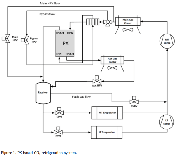
Figure 1 shows an example of a PX-based architecture for CO2 refrigeration. A subcooler is used between the gas cooler and PX. A part of the flow is used for subcooling the main gas cooler flow. The subcooled flow is passed to the highpressure inlet (HPIN) port of the PX. The flow from the HPIN expands and exits via the lower-pressure outlet (LPOUT) port as a two-phase liquid-gas mixture, similar to a high-pressure valve. The bypass flow used for subcooling is heated after crossexchanging the heat with the subcooler flow. Assuming perfect heat exchange, the temperature of the gas exiting the subcooler matches the temperature at the exit of the main gas cooler. The superheated gas is then input into the low-pressure inlet (LPIN) port of the PX. The gas comes out of the high-pressure outlet (HPOUT) port and rejects heat via the auxiliary gas cooler, which can be either a standalone unit or integrated into the main gas cooler. The two-phase mixture from the auxiliary gas cooler is then diverted to the receiver. The combination of subcooling and the expansion process in the PX leads to an overall lower quality in the receiver. Therefore, the amount of generated flash gas is reduced, lowering the work required for MT compressors.
System Modeling Methodology
For modeling, several relationships are assumed based on ideal PX behavior, and then the overall architecture is solved by considering mass and energy balance throughout the system.
Ideal PX Model
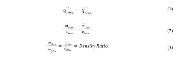
The architecture modeling method builds on the PX modeling method and operating principles described previously [8]. Essentially, the PX is a volumetric flow device, and the volumetric flows from the HPIN and LPIN ports must be equal, which implies that the mass flows are related to the density ratio between the high- and low-pressure sides. In a refrigeration cycle, the high and low pressures are dictated by the gas cooler pressure and receiver pressures, respectively. Thus, the density ratio and mass flow ratio are determined by the operating conditions. In the ideal PX model, the travel distance (a measure of the PX’s volumetric efficiency) [9] for the HPIN and LPIN ports is assumed to be 100%, leading to the following equations, which describe the relation between the volumetric and mass flow rates between high- and low-pressure sides.
The density ratio plays a significant role in the PX efficiency because it dictates the amount of LPIN flow that the PX can take in for a given HPIN flow. To determine efficiency, the entire gas cooler flow is assumed to pass through the HPIN port. It is advantageous if the LPIN flow can be maximized, thereby minimizing the amount of flash gas going to the MT compressor. The density ratio is also called the mass boost ratio) because it describes the relation between the LPIN and HPIN flows. In the ideal PX model, the density ratio and mass boost ratio are equal.
Furthermore, an ideal PX is assumed to have zero bearing flows, zero mixing, and no heat transfer between the inlet and outlet streams, or with the ambient environment [6, 7, 9]. This is not true in reality, and the extent of deviation from ideal behavior produces a proportional performance deficit. For example, testing has shown that 5%–10% of the high-pressure flow can contribute to bearing flow and leakage [6, 7, 9]. Based on this assumption, and considering the mass balance, energy balance, and exergy balance, the following relations are obtained for a PX:
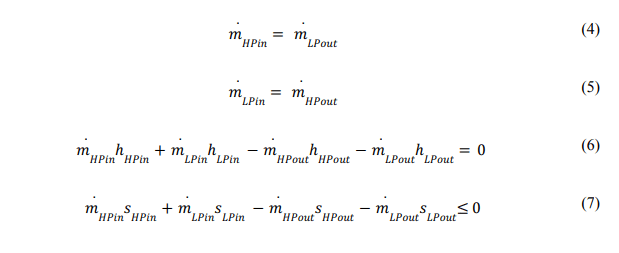
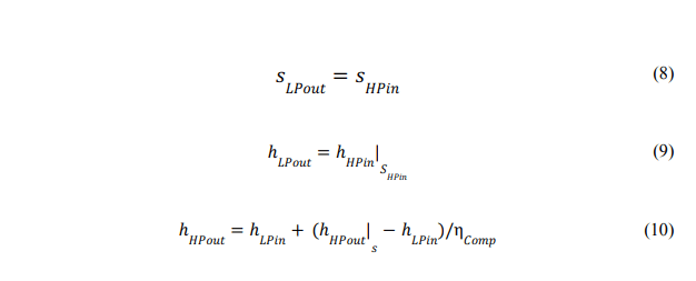
The ideal PX model satisfies the mass balance and energy balance and minimizes entropy generation. However, it is not an isentropic device because an equivalent volumetric flow (between HPIN and LPIN) results in unavoidable exergy reduction. It can be shown that the thermodynamic upper bound (minimal exergy loss) in an ideal PX is achieved when the expansion process is isentropic, and the compression process efficiency is determined by the first law of thermodynamics [8]. This results in the two following relations:
For any PX architecture, it is assumed that the pressure difference between the inlet and outlet of the PX is zero (HPDP = 0 and LPDP = 0). In reality, pressure losses of ~0.5–3 bar) have been observed, which result in reduced performance. Furthermore, the system is assumed to behave in an ideal fashion with no pressure losses in any of the pipes, all the valves are assumed to be isenthalpic, and the LT and MT compressors are assumed to have 75% isentropic efficiency and perfect mechanical efficiency. The system model is then constructed using the appropriate equations satisfying the mass and energy balances, and they are solved simultaneously to obtain the final system performance.
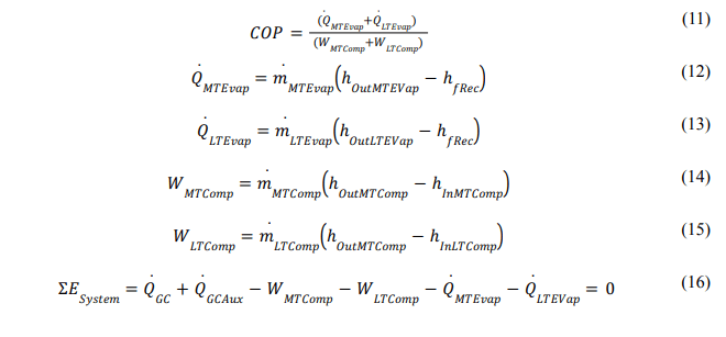
A few relations describing the overall system performance are described below:
Ideal System Model
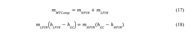
Specific to the presented architecture, a few more constraints are developed to solve the system of equations. In this architecture, the total gas cooler flow (or MT compressor flow) is split into the HPIN flow and bypass flow, which is also the LPIN flow. The subcooling amount (temperature difference) across the subcooler determines the amount of bypass flow required. The volumetric flows of HPIN and LPIN need to be equal, and the density ratio between the LPIN to HPIN ports must match the ratio of mass flow rates in these two ports. This leads to a unique set of solutions for a given gas cooler temperature and evaporator duty. The system of equations to be solved for the presented architecture is outlined below.
After solving for all the variables, the COP Lift for the PX-based system is calculated as follows:

Modeling Results and Discussion
The process described in the previous section is used for calculating COP and COP Lift for a typical gas cooler temperature ranging from 15 to 50°C. The system parameters used for these calculations are outlined below:
- MT Load = 120 kW
- LT Load = 30 kW
- Load split = 4:1
- MT evaporator saturation temperature = −8.3°C
- LT evaporator saturation temperature = −30.6°C
- MT compressor suction superheat = 16.7°C
- LT compressor suction superheat = 22.2°C
- MT & LT compressor thermodynamic efficiency = 75%
- Pressure differentials within PX (HPDP and LPDP) = 0
- Max gas cooler pressure = 96.5 bar
- Max receiver pressure = 38 bar
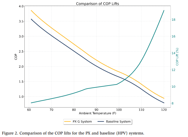
Figure 2 shows the COP of the PX and baseline valve systems, and the COP Lift is plotted on the right Y-axis. The COP Lift increases rapidly with increasing temperature, reaching as high as 18% around 48.9°C.
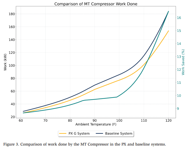
Similarly, the work saved by the MT compressor can be plotted (Figure 3) as the function of temperature, showing a similar trend; the work savings increase with increasing temperature. The baseline valve generates higher flash gas owing to the limitation on high pressure at higher temperatures. Typically, considering safety standards, the pressure at higher temperatures is limited to 96.5-100 bar, which is suboptimal. The PX can help overcome the deficiency due to this pressure limitation while maintaining higher work savings.
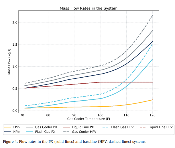
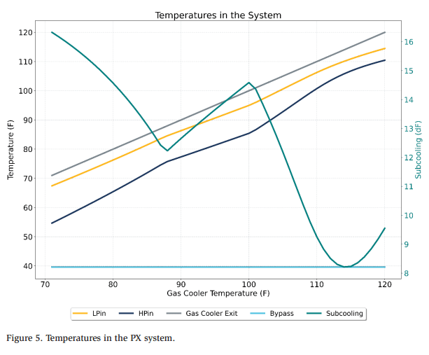
Other system parameters are plotted in Figures 4 and 5. Figure 4 shows flow rates through various nodes in the PX and baseline (HPV) systems. Note that the PXbased system helps reduce the overall gas cooler flow and flash gas flow, thereby providing a reduction in compressor work. The temperatures at different ports are shown in Figure 5, indicating that the LPIN temperature almost reaches the gas cooler temperature and helps to lower the HPIN temperature. The amount of optimal subcooling decreases with increasing gas cooler temperatures because of the relative distribution of the LPIN to HPIN mass flow rates. At lower temperatures, the overall HPIN flow is lower, and therefore, a given amount of LPIN flow can lead to higher subcooling.
Techno-Economical Analysis Based on Weather Patterns
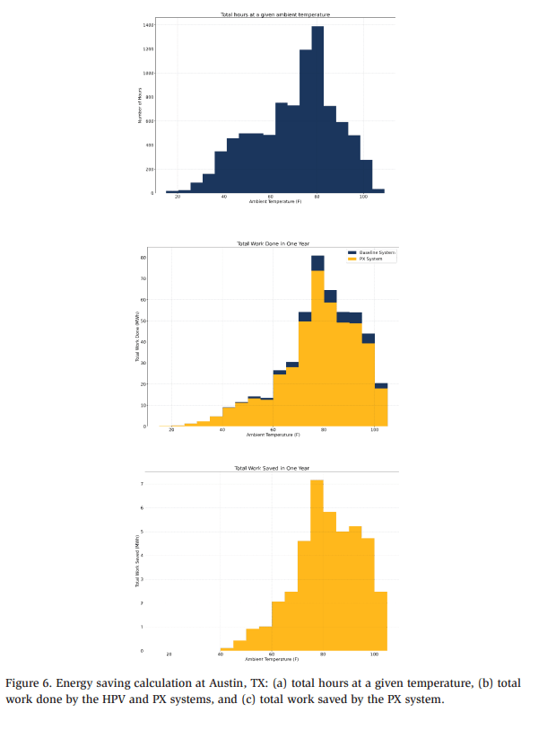
The COP Lift and work savings provided by the PX can be converted into an annual savings to give an idea of the power savings at a given geographical location. Figure 6 shows an example of a system used in Austin, TX. The hourly ambient temperature data is collected from an open source, namely Meteostat [10]. Figure 6(a) shows a histogram of the temperature profile, which gives a sense of how much time is spent in various temperature buckets. The COP vs. temperature curve is used for calculating the hourly work done using the HPV and PX systems in a given year, which is then used for calculating the annual work savings of the system.
The contribution of percentage work saved at higher temperatures against percentage time spent at those temperatures is shown in Figure 7. Even if the system spends less time at higher temperatures, there is still a significant contribution to the percentage of overall work saved. Therefore, technologies that maximize system performance at the higher end of the temperature spectrum, such as the PX, can provide a significant value.
Cumulative work saved from Figure 6 (c) gives an annual work saving for this system in Austin, TX, to be around 43 MWh/year. At warmer locations in the USA, estimated energy savings can be up to 63 MWh for a similar 120 kW MT and 30 kW LT system. Cost savings will depend on electricity rates at a given location. Furthermore, the addition of PX helps to add equivalent compressor capacity to the system and helps to handle extreme temperature scenarios without shutting down the entire store.

Effect of System Design Variations on Annual Savings
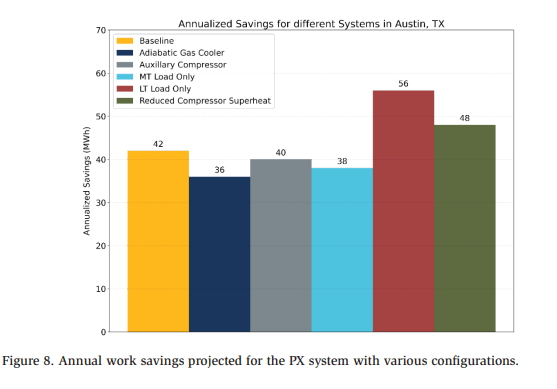
Several system design variations are also studied to assess their impact on annual energy savings. For each of these design variations, a detailed system model is built, and a system of equations is solved to calculate the COP for a baseline HPV system and PX system with the same design variation. The COP Lift and work saved are calculated and then converted to annual savings, as described above. The system designs studied include:
- Presence of adiabatic gas cooler (120 kW MT, 30 kW LT load)
- With parallel (auxiliary) compressor of 0.2 kg/s capacity (120 kW MT, 30 kW LT load)
- System with 100% MT load (150 kW MT, 0 kW LT load)
- System with 100% LT load (0 kW MT, 150 kW LT load)
- Reduced compressor superheat (15 F MT, 20 F LT for 120 kW MT, 30 kW LT load)
Figure 8 shows the effects of these system variations on the annual savings provided by the PX system. Note that despite these additional enhancements or variations in the baseline system, the PX still provides significant value. However, it may be useful to conduct a similar analysis before installing a new system at a particular location.
Practical Applications and Field Experience with Rotary Pressure Exchanger (PX) Systems
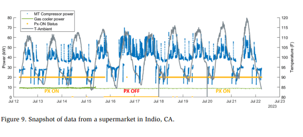
TC-CO2 refrigeration systems with PX have been installed at multiple supermarket locations in Europe and North America. A PX has been operated over several months in Milan, Italy, demonstrating over 30% energy savings while maintaining smooth control of the gas cooler pressure and handling loads of 40–180 kW and temperatures up to 40°C [11].
A PX system has also been installed in a supermarket in Indio, CA. Figure 9 shows a sample data set obtained from this installation, providing PX data for approximately nine days and baseline (valve) data for approximately two days. This store was also equipped with an adiabatic gas cooler. Comparing the PX and valve data, note that the density of points with higher compressor power is higher when the baseline system runs, but the concentration of points decreases as soon as the PX is operated. The histogram of total compressor power consumption indicates that the PX eliminates the need for an extra MT compressor during extreme weather conditions and helps reduce peak power consumption during intermittent periods by ~30%. Considering the average savings provided by the PX over this entire period, the average MT power consumption is reduced by ~14%, on top of the system with an adiabatic gas cooler.
Conclusions
This study reports on system architectures using a rotary PX for TC-CO2 refrigeration. The method used to predict the refrigeration performance while assuming an ideal PX is outlined based on first principles. These simulations demonstrate the potential of PX devices to improve the performance of CO2-based systems, especially at higher ambient temperatures. As CO2-based refrigeration systems become more prevalent and replace hydrofluorocarbon-based systems because of initiatives and protocols that combat climate change, PX-based refrigeration systems may play a pivotal role in improving system performance, thereby lowering operating costs. A PX-based system can also reduce MT compressor capacity and help reduce capital expenditures while maintaining the desired gas cooler pressure control and reliable operation. Refrigeration systems using the PX system have been installed in multiple supermarkets in Europe and North America, showing significant performance gains under a wide range of temperatures and loads.
References
[1] Kohsokabe, H., Funakoshi, S., Tojo, K., Nakayama, S., Kohno, K., 2006. Basic operating characteristics of CO2 refrigeration cycles with expander-compressor unit. International Refrigeration and Air Conditioning Conference, Purdue University, West Lafayette, IN. [2] Kakuda, M., Nagata, H., Ishizono, F., 2009. Development of a scroll expander for the CO2 refrigeration cycle. HVAC&R Research 15(4), 771-783. [3] Elbarghthi, A.F.A., Hafner, A., Banasiak, K., Dvorak, V. 2021. An experimental study of an ejector-boosted transcritical R744 refrigeration system including an exergy analysis. Energy Conversion and Management 238, 114102. [4] Barta R.B., Groll, E.A., Ziviani, D. 2021. Review of stationary and transport CO2 refrigeration and air conditioning technologies. Applied Thermal Engineering 185, 116422. [5] Thatte A., et. al. 2022, Rotary Gas Pressure Exchanger for Trans-Critical CO2 Refrigeration. 15th IIR Gustav Lorentzen Conference on Natural Working Fluids. [6] Thatte A., Fricke B., Nawaz K. Novel Rotary Pressure Exchanger for Highly Efficient Trans-Critical CO2 Refrigeration Cycle, Proceedings of 15th IIR-Gustav Lorentzen conference on Natural Refrigerants, 56, Trondheim, Norway, 2022. [7] Thatte A., Fricke B. New Types of Low Global Warming, Energy Efficient Refrigeration Architectures Using a Trans-Critical Rotary Pressure Exchanger, Proceedings of ASHRAE Annual Conference, TO-22-C041, Toronto, Canada, 2022. [8] N. Sarawate, A. Thatte, O. Samudrala, Novel Architectures for Transcritical CO2 Refrigeration Cycle Using Rotary Pressure Exchanger, GT2023-103228, Proceedings of ASME Turbo Expo 2023, Boston MA 2023. [9] Thatte A., Multi-Phase Rotary Pressure Exchanger as a Novel CompressorExpander for Increasing Efficiency of Trans-Critical CO2 Heat Pumps, Proceedings of ASME Turbo Expo 2023, GT 2023, Boston, USA, 2023. [10] https://meteostat.net/en/ [11] “ATMO America: Epta’s ETE Technology to be Installed in First U.S. Store, Says Kysor Warren” ( https://r744.com/atmo-america-eptas-ete-technology-tobe-installed-in-first-u-s-store-says-kysor-warren/