REDUCING AMMONIA REFRIGERANT CHARGE IN SKATING RINK REFRIGERATION SYSTEMS
CLAUDE DUMAS, CITY OF MONTREAL COSTAS LABOS, CITY OF MONTREAL CONSTANTINE PETROPOULOS, PBA2 VICTOR SANTANGELO, PBA
The information contained in the present document is provided by the authors only as indication, without implicit or explicit warranty. It is the user’s responsibility to validate the parameters applicable to the specific usage and make the necessary adjustments.Refrigeration designers for ice-skating rinks operated by the city of Montreal said that they were able to reduce the systems’ ammonia charge through a design that uses a liquid leg raised to the mid-height of the plate heat exchanger and employs what the designers’ report said is an innovative equilibrium vessel.
Montreal owns and operates 47 refrigerated skating rinks and aims to replace its systems that use hydrochlorofluorocarbon refrigerants that are being phased out by the Montreal Protocol.
The city is turning to ammonia refrigeration systems for the rinks, which are subject to stringent safety codes and guidelines. The report’s authors said the city’s installations exceed the “strictest of these standards” through the use of ammonia (air) washers in the machinery room, neutralization tanks and reduced ammonia charge.
The paper describes an innovation for the project consisting of an equilibrium vessel that is designed to simplify the system, minimize refrigerant charge, minimize controls and “avoid the need for a refrigerant operating level control and a high pressure receiver.”
So far, the city has completed work on 14 arenas, with 11 in the design stage and four under construction, with the entire project slated to be finished by 2020.
INTRODUCTION
The refrigeration industry is slowly returning to the use of ammonia as a replacement to the hydrochlorofluorocarbon based refrigerants such as R-22. These HCFC refrigerants are no longer the preferred choice of the refrigeration industry due to their environmental impact and will soon be phased out by government regulations adhering to international treaties (Montreal Protocol).
Ammonia is classified as a B2L3 type refrigerant which means it is both toxic and mildly flammable6 . To reduce the risk of exposure due to component failure, accident or human error, the installation must adhere to the stringent safety codes and guidelines published by CSA, IIAR, ASHRAE, the province and municipalities.
The city of Montreal has installations which exceed the strictest of these standards. The City’s initiative to lowering both the risk and the level of exposure includes, ammonia (air) washers in the machinery room in case of refrigerant leak, neutralization tanks and reduced ammonia refrigerant charge.
CRITICALLY CHARGED SYSTEMS
“…Critically charged system is a type of refrigeration system whose refrigerant charge is limited in such a way that if the entire charge is located in the evaporators, it is not possible for liquid refrigerant to be entrained in the compressor suction line.”
In this report we will explain the methods we applied to reduce the total refrigerant charge and to achieve a refrigeration system design containing only 2.25 lbs/TR.
The U-tube separator (1) assembly includes the liquid leg (7), the wet vapor riser (8) and the plate heat exchanger (evaporator) (2), designed to work with an equilibrium vessel (9), a level column (3) and a high level safety cut-out switch (4). The separator uses directional change, baffles and centrifugal action to achieve vapor / liquid separation. Compared to a conventional surge drum vessel, this U design occupies less physical space, is furnished pre-assembled and ready to install without the need of field erected support structure.
The refrigerant to brine plate and frame evaporator (2) was selected for optimum performance utilising gravity feed to thermosiphon motion and a mid-level liquid refrigerant charge. This partially flooded design optimizes refrigerant boil-off and vapor superheat. According to the plate manufacturer design engineers, «The flooded plate evaporator can be more efficient if the liquid leg level is up to mid height of the plate heat exchanger, maximising usage of the plate surface to produce phase change of the refrigerant». The brine flow was reduced to 451 usgpm (about ½ of the typical industry design) at 4o F temperature differential allowing for lower operating costs.
The 4 inch column (3) and sight glass assembly (13) allows visual liquid refrigerant level verification and charging calibration. Added to the column is a level float switch (4) which provides a cut-off protection against liquid carryover in the suction and refrigerant overcharge.
The oil pot (5) was selected for a volume (V5 ) equal to the volume of the liquid leg accumulator (6) x 1.1 (V6 *1.1 where accumulator volume = V6 ).
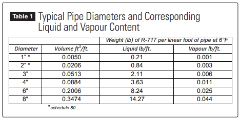
Table #1 illustrates pipe volumes and corresponding ammonia holding capacities for typical oil pot diameters.
The pre-assembled liquid leg (7) and wet vapor riser (8) are both 4” in diameter.
The equilibrium vessel (9) was designed like an accumulator and its role is to prevent liquid refrigerant from exceeding the maximum operating level (12) when the oil pot is completely filled with oil. The vessel volume (V9 ) = (V6 +V5 )*(1.1).
Sight glass (10) corresponds to the minimum liquid level (or ½ H where H=height of the heat exchange plates) for a correctly charged system with a refrigerant filled oil pot (5), whereas an oil pot filled with compressor oil would have a liquid ammonia level corresponding to sight glass (11). Should liquid exceed level indicator (12), the compressors must be immediately stopped and not permitted to operate until refrigerant charge (or anomaly) is corrected.
Service receiver is not shown (14). This vessel is not in the direct refrigerant flow containing only refrigerant vapor and used to stock liquid refrigerant when service conditions call for a system pump-down.
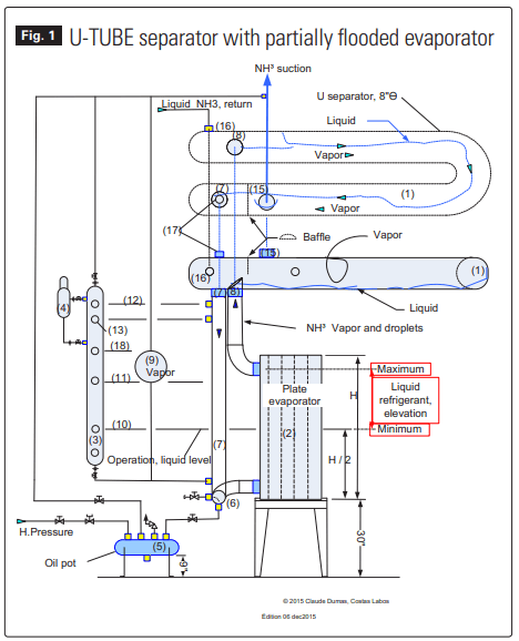
The suction port (15) is located at the top of the “U”-TURN separator, whereas port (16) identifies the liquid feed connection. The spare port (17) can accommodate the level sensor of an electronic transmitter (not used). Sight glass (18) corresponds to the top (crown) of the equilibrium vessel.
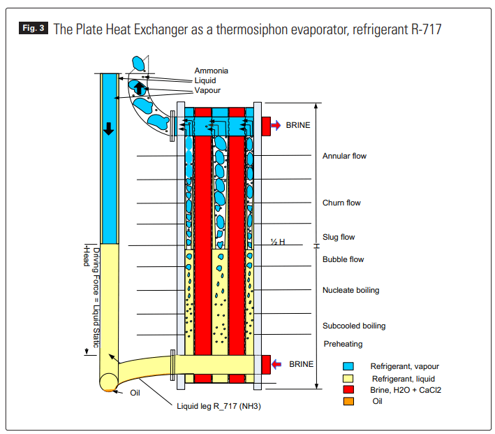
The liquid refrigerant and brine enter the heat exchanger at ports (6) located at the bottom and move upwards in a co-current (parallel) flow. The co-current flow permits a more significant refrigerant phase change at the base of the heat exchanger. The figure 3 also shows the collection of oil in case of insoluble oil heavier than the refrigerant.
INNOVATION
The innovation in this project is the use of an equilibrium vessel (9) designed to simplify the refrigeration system, minimize refrigerant charge, minimize controls, and avoid the need for a refrigerant operating level control and a high pressure receiver.
THE RISK VS. THE REFRIGERANT CHARGE
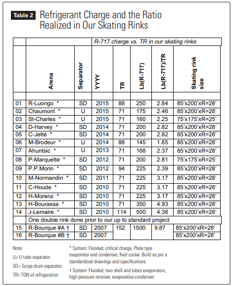
The first project for which the City implemented its policy to use ammonia as an alternative refrigerant in an indoor Arena was the Arena Raymond Bourque. The two rinks’ refrigeration system used two flooded shell and tube evaporator (one for each rink), a high pressure refrigerant receiver, an evaporative condenser and an ammonia charge of 1500 lbs. See Table 2, Arena R-Bourque.
Given the amount of ammonia introduced to the arena’s refrigerant system and the refrigerant’s toxic nature, a risk assessment study was commissioned.
The report confirmed the direct link between the level of risk and the quantity of ammonia present in a system and recommended that “…priority be given to minimizing the refrigerant charge, thus reducing the risk from an accidental leak”.
With ammonia reduction in mind, the move to drastically decrease the refrigeration charge came quickly – the critically charged design was introduced.
First we listed and identified all the refrigeration components and specifically tagged those with large volume or ammonia stocking potential (ex: surge drum [level], shell and tubes evaporators, evaporative condenser, high pressure receiver, oil pot, piping carrying liquid, liquid leg, sight glass column, etc).
In our design we:
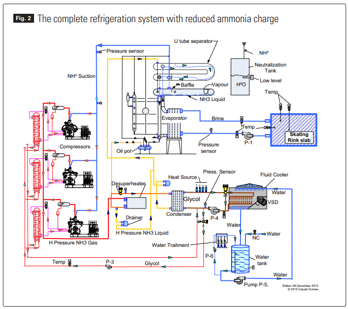
- Replaced the evaporative condenser by an ammonia to a glycol (solution) plate heat exchanger coupled with a glycol solution fluid cooler.
- Replaced the shell and tube condenser by a compact welded plate heat exchanger.
- Selected a plate and frame evaporator for optimal efficiency in a thermosiphon mode and partial flooded condition.
- Replaced the conventional surge drum and related supporting structure with U-tube separator thus reducing the space footprint and installation time.
Note:
–Given the critically charged design, neither the U-tube separator nor a conventional surge drum should contain liquid refrigerant.
— The designer is not obliged to use the “U” separator to achieve the efficiency of a critically charge refrigeration system like ours.
- Eliminated two isolation valves used for service (and calibration) between the evaporator and surge drum. This allowed smaller liquid leg and wet riser piping (reduced from 6” to 4”), thus reducing the refrigerant charge.
- Eliminated the operating level control.
- Modified the piping and removed the high pressure receiver from its initial as a charge balancing function to simply a service receiver, thus under normal operating conditions containing vapor only.
- Introduced an equilibrium vessel to account for level function resulting from oil displacing liquid ammonia in the oil pot.
- Specified two independent refrigeration systems, 71 TR each, for two rink arena. This allows separate refrigerant charge (less than 175 lbs/system), smaller emergency ventilation system, minimizing the risk and less refrigerant loss in the event of a complete circuit leak.
- educed the oil pot from an 8” to a 4” diameter, thus reducing its holding volume by 75%.
- Reduced liquid carrying pipes diameters and length.
For example, at 6o F one linear foot of a 4” pipe can contain 3.63 lbs of liquid ammonia whereas one linear foot of an 8” pipe can contain 14.27 lbs of liquid. Refer to Table 1 for typical pipe diameters and corresponding liquid and vapour content.
Montreal owns and operates 47 refrigerated skating rinks of which 41 are located indoors and 6 are located outdoors. Presently, 14 arenas have been completed, 11 are in design stage and 4 are now under construction. Eleven more will be added to the list and respecting the HCFC-22 phase-out protocol – completion is expected by year 2020.
The 14 ammonia rink refrigeration systems designed, built and commissioned are listed and shown on Table 2, mostly sized for 71 TR capacity and varying quantities of refrigerant with the more recent charged with less than 175 lbs of ammonia (a ratio of 2.46 lbs/ TR). Furthermore, three (3) are noteworthy: Ahuntsic, where we realized a charge of 168 lbs for 71 TR (a ratio of 2.37 lbs/TR); M-Brodeur, where 145 lbs for 88 TR (a ratio of 1.65 lbs/TR) were used; and Saint-Charles where the charge was set at 160 lbs of ammonia for 71 TR (a ratio of 2.25 lbs/TR). See Table 2 for the refrigerant charge and the ratio realized in our skating rinks.
Our focus over the past several years, and fourteen (14) skating rink refrigeration systems completed, was always to reduce the risks through prudent design and implementation aimed at minimizing the ammonia refrigerant charge, surpassing industry standards and never compromising safety and performance.
On numerous occasions we needed to guide the industry players, whether they were suppliers or contractors, towards changing the paradigm that more is better does not apply to critically charged refrigeration systems. Many times we gave order to the contractors to remove excess refrigerant in the system.
Note:
U= U tube separator.
SD= Surge drum separator.
TR= TON of refrigeration
* System: Flooded, critical charge, Plate type evaporator and condenser, fluid cooler. Build as per a standardized drawings and specifications.
† System: Flooded, two shell and tubes evaporators, high pressure receiver, evaporative condenser.
CONCLUSION
The use of a factory supplied U-tube separator assembly, with a compact liquid and wet vapour riser and a simple-fit to the top of the plate heat exchanger frame, facilitates the installer’s job, minimizes the space footprint and reduces installation time. See Fig. 2.
The use of an equilibrium vessel (9) is our innovation; an added protection designed to accommodate refrigerant mass displaced by oil migration and safeguard the compressors from potential liquid slugging. This design minimizes refrigerant charge and avoids level feed controls.
The designer is not obliged to use the “U” separator, he can use a surge drum to achieve the efficiency of a critically charge refrigeration system like ours – simply follow the outlined instructions. A surge drum would have a larger foot print and require an added support structure; however, an equilibrium vessel would not be needed.
To reduce the risk (from ammonia exposure), we have prioritized the need for and the commitment to minimizing the ammonia charge in the refrigeration system; this is why in adjusting the liquid leg, the liquid evaporator level and introducing the equilibrium vessel, we have significantly reduced the refrigerant charge from many of our systems.
The message to remember is:
The flooded plate evaporator can be more efficient if the liquid leg level is up to mid height of the plate heat exchanger, maximising usage of the plate surface to produce phase change of the refrigerant. This is a revelation coming from the design engineer working for a plate manufacturer. See Fig. 3.
REFERENCES:
Ammonia refrigerant is identified by ASHRAE Standard 34 as number R-717, incidentally its molecular weight is 17 while its formula is NH3 .
PBA is the consulting engineering firm Petropoulos, Bomis & Assoc. Inc. experts in ammonia refrigeration.
ASHRAE Standard 34-2013,
Page.9, TABLE 4-1,. Refrigerant Data and Safety Classifications.
Page16, FIGURE 6.1.4,. Refrigerant Safety Group Classification….. A2L and B2L are lower flammability refrigerants with a maximum burning velocity of ≤ 3.9 in./s (10 cm/s).
In accordance with CSA B52-13, P. 18,
For more information about our refrigeration systems go to the following webpage: http://pages.videotron. com/NH3/text/publications_cdumas. html. The title of the file is: « Mise aux normes du système frigorifique de l’aréna Ahuntsic, Réfrigérant R-717.»
Lecompte Michel «Nouvelles normes de réfrigération», ASHRAE-Montréal conférence, 11 Janvier 2016, page 20/32, «EPA, Alternatives for Refrigeration Applications»