Pressure Relief Design Considerations From a PSM Compliance Standpoint (Part One)
Bill Lape, SCS Engineers
Pressure relief design documentation is often the most misunderstood portion of the Process Safety Information required under 29 CFR 1910.119(d) (3)(i)(D) and 40 CFR Part 68.65(d)(1) (iv). The two regulations state that the relief system design AND design basis shall be included in the process safety information pertaining to the equipment in the process.The word “design” is fairly straightforward. The Cambridge Dictionary defines the word design, when used as a noun, as “a drawing or set of drawings showing how a … product is to be made and how it will work and look” or “the way in which something is planned and made.” Sounds simple, right? We need to have the technical specifications and physical arrangement of the relief design documented. Easily done.
Hold that thought for a moment. Before we dive into the pitfalls associated with the documentation of the physical arrangement and technical specifications for the relief system, let’s consider what the regulation means by the “design basis.” In the strict sense, the “design basis” of a design is the set of codes and standards that were used to determine the design. For instance, a facility with a relief vent header that was constructed in 1997 would likely have followed ASHRAE15, 1994 Edition. If the facility modified their vent header in 2016, the header design basis would be updated to IIAR2, 2014 edition. These design bases need to be listed in the design documentation.
Circling back to the design documentation, the ASME Boiler & Pressure Vessel Code (B&PVC) requires that the user “conduct a detailed analysis to identify and examine all potential overpressure scenarios.” It goes on to say that the causes of overpressure as described in API 521, Pressure Relieving and Depressurizing Systems, shall be considered, but that “other standards or recommended practices that are more appropriate to the specific application may also be considered.” Some of the scenarios listed in API 521 that can be relevant to ammonia refrigeration systems include closed outlets on vessels, cooling water failure to condenser, accumulation of non-condensables, overfilling of a storage or surge vessel, failure of automatic control, abnormal heat or vapor input, a heat exchanger leak, hydraulic expansion, exterior fire, and a power failure.
We need to start by documenting the required relief capacity for each piece of equipment for each relevant scenario as determined by the facility’s Process Hazard Analysis (PHA). Bear in mind that a scenario is not irrelevant if we deem them to be improbable due to the engineering (e.g. high pressure alarms and cutouts) and administrative (e.g. periodic inspections and operating procedures) safeguards that are in place at our facility. The two scenarios of overpressure that are most commonly identified for ammonia refrigeration equipment include an exterior fire or an abnormal heat or vapor generation, perhaps due to a closed valve, with exterior fire generation being the scenario that is most often documented in the relief design. We’ll look at each one individually to illustrate some of the pitfalls associated with determining the required relief capacity.
Let’s start by looking at how the relief capacity is determined for an exterior fire. The formula to calculate this relief capacity for a vessel or pipe is:
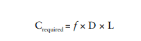
Where:
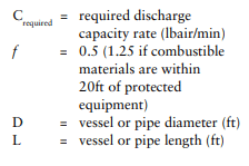
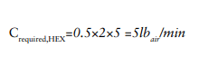
Let’s say that we have a shell and tube heat exchanger. The heat exchanger has a diameter of 2 ft and a length of 5 ft. Let’s assume for the sake of argument that there are no combustibles within 20 ft. The required relief capacity using the formula would be:
What if the unit is outdoors and is insulated and jacketed with an aluminum jacket? The reduced likelihood of a fire around the unit due to its location, together with the reduction in heat load due to the reflective properties of the insulation jacket along with the F factor of the insulation, need to be considered. While a mathematical treatise on how to determine an appropriate reduction factor in required capacity due to insulation and location is outside the scope of this article, it is important to be aware of these factors as they will occasionally make a huge difference in the cost of the relief system for certain pieces of equipment. For the purposes of this exercise, let’s say that this heat exchanger is located indoors, so we are going to assume that there is no attenuation of the heat load presented by a fire around the equipment.
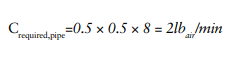
Let’s take the external fire scenario a step further. For the purposes of illustration, assume that the heat exchanger has 8 ft of 6” diameter piping attached directly to the suction outlet of the heat exchanger prior to the suction isolation valve. The required relief capacity for this pipe must be included in our calculation as it is part of the protected equipment. The required relief capacity of the pipe is:
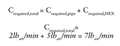
The total required relief capacity for this equipment would then be:
While the change to the required relief capacity in this illustration would be unlikely to change the selected relief valve, consider a product tank with a flooded ammonia refrigeration jacket. In order to properly calculate the total required relief capacity, not only does the surge drum need to be included, but the tank jacket, the liquid drop leg, and the jacket suction return piping to the surge drum also need to be included in the total required relief capacity. Often these additional pieces of equipment within the envelope of relief valve protection are omitted from the calculations.
Another area that is often overlooked is the potential relief scenarios due to internal heat loads. While internal heat loads are unlikely for most pressure vessels in an ammonia refrigeration system, they are a consideration for heat exchangers. If a heat exchanger will be exposed to a fluid that is above the saturation temperature of ammonia that corresponds to the set pressure of the relief valves that are installed to protect it, then the internal heat loads must also be considered. For instance, if the set pressure of a surge drum on a product tank is 150psig, the corresponding saturation temperature is roughly 85°F. Most clean-in-place (CIP) systems for product tanks will have a high temperature cutout for their wash cycles between 140°F and 180°F, depending on the application. This temperature is well above the saturation temperature of the ammonia at 150 psig, and, as such, the internal heat load must be considered. It is outside the scope of this article to dive into the math behind the internal heat load calculations, but the following example provides illustration of how the internal heat load can often be the true factor in determining the required relief capacity of equipment.
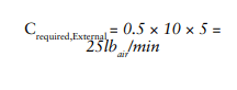
Let’s say that we have a product tank that, while not flooded, is built to the ASME B&PVC, so it must be protected with relief valves. Its refrigeration jacket is 5 ft high and the tank is 10 ft in diameter. It is rated for 150 psig Maximum Allowable Working Pressure (MAWP). To be conservative, no attenuation factor will be used for heat loads due to external fire, even though it is insulated and located outdoors. There are no combustibles within 20 ft of the tank. The required capacity for the external heat load is:
However, the tank is cleaned by a CIP system that washes the tank with a maximum flow rate of 125 gallons per minute of wash solution. The high temperature cutout on the CIP system is 180°F. The required relief capacity due to internal heat load would be:
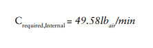
As you can see, the required relief capacity due to internal heat load is the relief capacity scenario that determines the capacity of the installed relief valves on this equipment. As an end user with an ammonia refrigeration system, is important to be mindful of these internal heat loads and their impact on relief capacity, as this particular scenario has often been overlooked when the relief system design is documented.
Another parameter that is often omitted from relief designs is an analysis of inlet losses between the protected equipment and the relief valve. In a nutshell, the piping between the protected equipment and the relief valve will cause a pressure drop between them. The effect of this pressure drop is to de-rate the capacity of the relief valve. Section UG-135(b)(1) of the ASME B&PVC requires that “…The characteristics of the upstream [pressure relief] system shall be such that the pressure drop will not reduce the relieving capacity below that required or adversely affect the proper operation of the pressure relief valve.”
So, in order to comply with the ASME B&PVC, two things must be true of the inlet losses:
The required relief capacity must be less than the de-rated capacity of the pressure relief valve due to the inlet pressure loss. The inlet pressure loss must be less than the blowdown pressure of the relief valve or the relief valve will chatter during operation, reducing its flow.
Let’s look again at our product tank example. We determined that the required relief capacity is 49.58 lbair/min. The tank has no nozzle on it dedicated for relief, but let’s say that its jacket suction outlet connection is 1-1/2.” We cannot install a relief connection greater than 1-1/2,” but ½” or even ¾” is undesirable due to its relative lack of strength and potential for breakage. So, we choose a 1” nozzle to connect the relief valve inlet piping to the tank suction line. Let’s say that a commercial refrigeration relief valve is chosen with an inlet port size of 1” and a relief capacity of 53.8 lbair/min.
Since there is an isolation valve in this suction line within a foot of the jacket nozzle on the tank, the connection must be made within six inches of the tank suction outlet. However, the alcove of this tank where the operator inspects it and makes connections to pump product in and out of the tank is on the second floor of the facility, so the tank is mounted on a steel framework, putting this nozzle out of reach of the refrigeration operators. So, upon installing this tank, the operators decide to extend the relief valve inlet piping up to the roof to facilitate the inspection and maintenance of the relief valves. They install 25 ft of 1” piping, with one 90° elbow, and a three way valve with a Cv of 13.95 gpm/psi. When we calculate the de-rating of the relief valve capacity, we find that the adjusted capacity is 43.44 lbair/min, which is inadequate to cover our required relief capacity.
One might argue that such a piping arrangement for the inlets of relief valves is unusual. Admittedly, it is. However, it serves to illustrate how important it is to evaluate the inlet piping and its effect on the relief valve capacity. The purpose of this article was to highlight some of the factors that affect the relief capacity of a relief system that are often overlooked. In the next article, we will discuss some of the pitfalls associated with internally relieving relief valves.