PARALLEL OPERATION OF SCREW COMPRESSOR PACKS
B. PIJNENBURG AND J. RITMANN
BITZER KÜHLMASCHINENBAU GMBH, JENS JUULS VEJ 16, 8260 VIBY J. AARHUS, DK
E-MAIL: BAS.PIJNENBURG@BITZER.DE, JOHN.RITMANN@BITZER.DE
ABSTRACT
Ammonia screw compressor packs utilizing parallel operation of two or three smaller industrial NH3 screw compressors offer the optimum way to fulfill maximum part load efficiency, increased redundancy, and other highly desirable features in the industrial refrigeration industry. Optimized parallel operation can secure continuous operation and can in most applications be configured to improve overall operating economy. New compressors have been developed to meet requirements for flexibility in operation and have intelligent controls. The intelligent control system must focus on all external demands and strive to offer always the lowest possible absorbed power, including future scenarios with connection to smart grid. This paper builds on and includes most of the results of an earlier investigation to show how to implement a series of compressor packs following basically the results of these findings.
Introduction
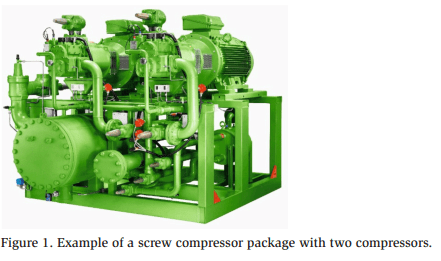
Ammonia compressor packs are typically equipped with one or more compressors. Figure 1 shows an example of a two-compressor pack. The compressors can be equipped with variable speed drive (VSD). A study about parallel operation of screw compressors for industrial ammonia refrigeration describes the optimum way of configuring packs with multiple compressors (Pijnenburg and Ritmann 2015). The findings from this study define the overall design criteria for highest possible partload efficiency over a wide range of capacity. The first part of this article analyzes that same study, including the different methods of capacity regulation, the method for evaluating total efficiency, and the comparison between different numbers of parallel operating compressors.
Maintaining high efficiency is one of the most important criteria for industrial refrigeration customers. Operational safety and reliability are other important criteria that emphasize the need for a certain amount of redundancy. Often the customers’ products or output from processes are far more expensive than the additional cost of securing proper back-up of their cooling system. Packs with multiple compressors offer high redundancy, in terms of having more smaller compressors and drive systems, thereby ensuring that the unit can continue to deliver cooling capacity, even during planned service or unforeseen repair in case of failures. Naturally, maximum up-time and minimum unintended stops have high priority in the industrial refrigeration system. This paper describes some of these requested redundancy features.
A dedicated control system is needed to fully utilize the advantage of parallel operation, both regarding efficiency and redundancy. The control system shall ensure maximum efficiency and operational reliability, when operating inside and even outside the compressor application limits, in the whole capacity range. The control system must focus on all external demands, yet strive to offer the lowest possible 2017 IIAR Natural Refrigeration Conference & Heavy Equipment Expo, San Antonio, TX absorbed power, including the future ability to respond to smart grids or variations of the electricity pricing during night and day.
Common Methods and Requirements for Capacity Control Systems
Different methods exist to control the capacity of a compressor system. The quality of the capacity control systems can be measured with different parameters:
- The ability to adapt the capacity to the cooling demand accurately, i.e., how well a certain suction pressure set point can be followed;
- The influence on the efficiency of the compressor and the drive line, i.e., how much the coefficient of performance (COP) of the system is affected;
- The requirements of and load on the power supply;
- The possibility to cover a large capacity range between minimum and maximum load;
- The cost of the capacity control system;
- Operational reliability; and
- Noise and vibration levels.
- The cost of the capacity control system;
- Operational reliability; and
- Noise and vibration levels.
BITZER (2014) provides a thorough description of different methods of controlling the capacity of a compressor system. Here only those methods used in the analysis later in this article are briefly described:
- On/off cycling,
- Speed variation (variable speed drive), and
- Slide valve regulation.
The first two methods are not incorporated in the compressor itself, but concern how to operate it. The last method requires a specific construction inside the compressor. The first method offers stepwise control, whereas the other two methods enable continuous variation of capacity. Each method is described briefly in the following sections, but Blumhardt (2006) details a comparative study on speed and capacity slide control for screw compressors
On/off cycling
On/off cycling is the simplest way to vary capacity. In simple systems, it can lead to large variation in operating condition and high cycling rates. It can make sense on systems with small load variation or large system buffer capacity. The ability to regulate capacity precisely with this method improves with the amount of parallel mounted compressors.
Speed regulation
The flow through the compressor varies with the rotational speed of the rotors. The speed-regulated screw compressor requires a specific drive line with a VSD. In most cases the speed regulation does not require changes to the compressor itself, but it affects the way the compressor operates.
Slide valve regulation
A slide valve parallel to the rotor shaft can be moved to create an internal bypass. Just before the gas is compressed in the rotor cavities, it can bypass internally to the suction side. The slide valve system makes a fairly simple and robust system for both stepwise and step-less variation of capacity. The slide valve regulation will also affect the volume ratio (VI) of the compressor. The influence on VI depends on the design of the compressor and the operating conditions. Some compressor designs are capable of independent regulation of capacity and VI.
The variation of capacity can influence both the volumetric and isentropic efficiency of the compressor. How much efficiencies are affected differs for each method and also depends on the operating conditions and the construction of the compressor. Volumetric efficiency relates to actual swept volume. In this article the term part load index (λ) is used to indicate the ratio between actual volume flow (at a certain load) and the nominal swept volume at maximum capacity (full load). Variation of capacity will also influence the efficiency of the drive line (motor and or VSD).
Description of Efficiency of Capacity Control Methods
The efficiency of the compressor, the motor, and the VSD can each be expressed as a function of some form of capacity (not necessarily the system cooling capacity). The efficiency of the compressor, the motor, and the VSD can each be expressed as form of graphs, tables, or polynomial functions. The total efficiency of the system can be obtained by coupling the performance data of different components in series and/ or in parallel. The relation between cooling capacity and system efficiency cannot be obtained directly from the supplied performance data, but requires some calculation. The relation will also depend on the operation condition of system (evaporating and condensing temperatures).
Figure 2 shows typical dependencies of the compressor part load index (λ) and isentropic efficiency (ηc) for a typical chiller condition (T0/Tc = +5/+35 °C / +41/95 °F). The left figure shows the efficiencies as a function of capacity slide valve position (CR), and the right figure shows them depending on compressor shaft speed. The software to calculate compressor performance (BITZER 2016) contains data based on extensive measurements with different compressor models over the whole range of operating conditions, shaft speeds, and capacity slide positions.
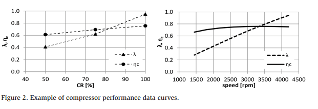
Figure 3 shows a typical dependency of motor (ηm) and drive efficiency (ηd), depending on the ratio of shaft torque to nominal motor torque (T/Tn), for three different shaft speeds (1,200; 2,400; and 3,600 rpm). Motor and drive data are calculated with software from a major global supplier of motors and variable speed drives.
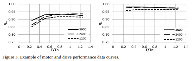
The graphs show that cooling capacity is not mentioned directly. It must be derived from the performance data and the actual operating conditions of the system.
The capacity regulation systems can have other positive or negative effects on system performance, other than on energetic efficiency. Some of these effects include
- Potential for increased capacity with operation at speeds above synchronous with VSD
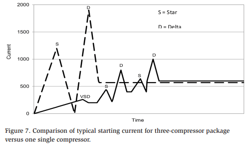
- Built-in soft-start function in the VSD resulting in low motor and power supply load at start-up.
- Positive displacement compressors that require practically constant torque over the complete speed range. Therefore voltage vs. frequency ratio of the VSD must be constant. A VSD can normally not supply voltages above the supply voltage, which means that the motor will be supplied with “under-voltage” during operation above synchronous speed. This means it cannot supply the full torque, limiting the possible operating conditions of the compressor in this speed range.
- Operation with economizer that can be utilized for a large capacity range with speed regulation for most compressor designs. The economizer port is normally closed very early in the unloading process on compressors with slide valve regulation in combination with a fixed economizer port.
- Parallel compounding, which will require smaller compressors to deliver the same maximum capacity.
- Compressor, motor, and drive efficiency that will increase to some degree with size
- Parallel compounding that automatically gives redundancy.
- Complexity of systems that increases with the number of compressors and combination of different regulation systems.
Method of Part Load Efficiency Evaluation
The part load efficiency of a compressor system can be evaluated based on the performance data of the components and the equations described in this section. The definitions and units for each symbol used in this section are listed in the nomenclature at the end of this paper. Equation (1) defines the cooling capacity that a screw compressor can deliver:

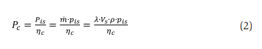
Equation (2) defines the shaft power of a screw compressor:
Equation (3) defines the electrical power consumption of the screw compressor package:

Equation (4) defines the COP of the screw compressor package:
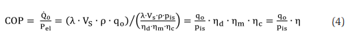
Plotting the COP as a function of the cooling capacity ( ) is the traditional way to evaluate the part load performance. The previous equations show that for a certain operating condition and for a certain size of compressor system, a linear relation exists between the cooling capacity and the part load index (λ) and between the COP and the energetic efficiency (η). By showing the energetic efficiency as a function of the part load index we have a way to show the part load performance on a dimensionless scale from 0 to 1, which makes it easy to compare for different operating conditions and different sizes of systems.
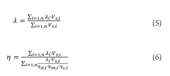
The total part load index and energetic efficiency for a compressor package with multiple compressors can be found from the weighted sum of the individual efficiencies according to Equation (5) and Equation (6).
The performance data curves (Figure 2) show that part load index (λ) and energetic efficiency (ηc ) for a compressor can be controlled by two parameters: speed and capacity slide position. Operating conditions are assumed to be constant in this paper, but they can also depend on capacity, i.e., evaporating temperature will rise as evaporator load decreases.
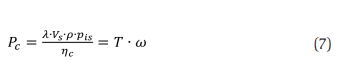
The energetic efficiency of the motor (ηm) and the VSD (ηd) depend on speed and torque (as seen in Figure 3). The torque and, in case of VSD, the speed will vary with capacity. The compressor shaft power relates to the torque and speed according to Equation (7).
The shaft speed is either constant or controlled actively, thus the shaft torque depends only on compressor part load index, energetic efficiency, and speed. A motor is typically selected with approximately 10% torque reserve at maximum (or nominal) load, giving the torque at maximum system load as 90% of the nominal motor torque (T/Tn = 0.9). The factor 0.9 is not constant and differs based on the available motor sizes and application type. Equation (8) defines the part load torque of the motor relative to its nominal torque:
The shaft speed is either constant or controlled actively, thus the shaft torque depends only on compressor part load index, energetic efficiency, and speed. A motor is typically selected with approximately 10% torque reserve at maximum (or nominal) load, giving the torque at maximum system load as 90% of the nominal motor torque (T/Tn = 0.9). The factor 0.9 is not constant and differs based on the available motor sizes and application type. Equation (8) defines the part load torque of the motor relative to its nominal torque:

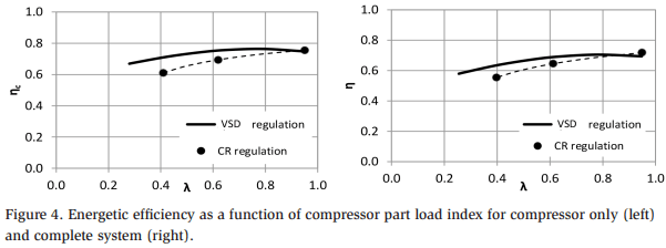
The part load performance, described by the dependency between part load index and energetic efficiency, can be derived quite easily from the compressor performance data. By combining Equation (8) with interpolation of motor and drive performance data, deriving the part load efficiency of the motor and drive as a function of the part load index is also possible. Figure 4 shows an example of the relation between the part load index (λ) and the energetic efficiency (η).
Comparison of Different Solutions
This section compares the part load performance of different compressor package solutions. The most basic compressor regulates solely with a slide valve. The next step is to add a VSD and finally to use multiple compressors. Simulations of many different solutions were done to map the different combinations.
All comparisons are done for the same total maximum capacity. For easy comparison, the values for part load index were scaled (indicated by λs) to be exactly one at maximum capacity. The effect of size, where larger machines tend to have better efficiency, is accounted for by using actual performance data from appropriate sizes of compressors, motors, and drives. The effect of size and the effect of using a VSD become evident when looking at the nominal maximum load efficiency. Multiple smaller compressors will have a slightly lower maximum load efficiency when compared with fewer larger compressors. Solutions with VSD will have a slightly lower maximum load efficiency than comparable size compressors without. The losses in a VSD on multiple compressor systems naturally only affect the one compressor with VSD.
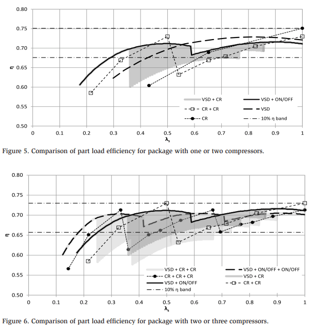
Figure 6 compares a solution with either two or three compressors. Again, solutions with VSD evidently have a constant high efficiency. The solution with three compressors (one VSD) can even keep very high efficiency down to approximately 17% capacity. Furthermore, a three-compressor solution with only slide regulation 2017 IIAR Natural Refrigeration Conference & Heavy Equipment Expo, San Antonio, TX (CR) has a high efficiency down to approximately 23% capacity, except from a minor load area around 37– 43%.
The analysis of the different scenarios was done for operation at a fixed operating condition (T0/Tc = +5/+35 °C / +41/95 °F). The results will change depending on the operating conditions, which should be considered when searching for the optimum solution. The results for low-temperature operation are not elaborated here, but will have a tendency to show lower maximum efficiency and larger drop in efficiency at part load. This is basically due to the relatively larger increase in losses
Reliability through Redundancy
The simplest configuration of a multiple compressor pack, with two parallel compressors (without VSD), already offers full redundancy on the complete compressor-motor unit. Both can operate independently and provide the ability to service one compressor-motor unit, while the other continues to operate and deliver 50% of the maximum cooling capacity. The three-compressor variant naturally offers an even higher level of redundancy. The redundancy offered by multiple compressor motor units is expressed in terms of
- Pack design that enables the exchange of a complete compressor-motor unit, without stopping the other(s).
- Multiple use of smaller compressors and motors. These compressors, motors, starter equipment, etc. are typically more feasible in terms of cost and are more readily available than the comparable larger ones. This means lower cost in case of stocking spare parts for unforeseen cases or typical shorter delivery times.
- Redundant sensors on critical positions. Each compressor can come with its individual set of pressure and temperature sensors. The oil management system can also be equipped with redundant oil pressure and temperature sensors.
For even higher reliability the redundancy can be increased by adding more compressor-motor units, or by using two parallel units (each with two compressors) instead of, for example, one pack with four compressors. The parallel units will give internal volume ratio; the oil return system; and other related functions. The separate distributed module philosophy can also be used for other main components in the system, like oil management system and switch board.
The distributed modules must all be able to work independently to ensure maximum redundancy. At the same time, the communication among the individual modules increases the potential to optimize the use of each individual component and to ensure maximum efficiency of the entire system.

Conclusion
Parallel compressors, where one is optionally fitted with VSD, provide high redundancy and high efficiency over a wide capacity range. The three-compressor package offers the highest level of redundancy and high part load efficiency over redundancy and high efficiency over a wide capacity range. The three-compressor package offers the highest level of redundancy and high part load efficiency over capacity range is seldom needed. A pack with two compressors provides basic redundancy, which naturally increases with more compressors. A control system with distributed modules fits the potential parallel operating compressors offer. The control redundancy, which naturally increases with more compressors. A control system with optimum way under all circumstances with respect to efficiency and reliability.
Nomenclature
COP Coefficient of performance [-]
CR Capacity slide regulation position [%]
η Total energetic efficiency of the compressor package [-]
ηc Isentropic efficiency of the compressor [-]
COP Coefficient of performance [-]
CR Capacity slide regulation position [%]
η Total energetic efficiency of the compressor package [-]
ηc Isentropic efficiency of the compressor [-]
ω Shaft rotational speed [rad/s]
n Subscript to indicate nominal values at maximum load [-]
References
BITZER. (2016). “Performance data for screw compressors.” BITZER Software v. Sindelfingen, Germany.
BITZER. (2014). “Competence in capacity control.” BITZER publication A-600-5, Sindelfingen, Germany.
Blumhardt, R. (2006). “Capacity control of screw compressors: Speed or slide control—A comparitive study.” BITZER publication SV-0402-GB, Sindelfingen, Germany
EN12900:2013 Refrigerant compressors – Rating conditions, tolerances, and presentation of manufacturer’s performance data, European Committee for Standardization, Brussels, 2013.
Pijnenburg, B.,and J. Ritmann. (2015). “Parallel operation of NH3 screw compressors—The optimum way.” Presented by BITZER at IIR Ohrid Macedonia, 2015.