MAXIMIZING EFFICIENCY OF CARBON DIOXIDE REFRIGERATING SYSTEMS
S. Forbes Pearson, Star Refrigeration Ltd, Glasgow G46 8JW
Introduction
The return of Carbon Dioxide as a refrigerant is probably un-stoppable because it is much more environmentally friendly than most of the non-flammable, non-toxic refrigerants currently in use. However, it is worth considering the reasons why industry departed from it in the 1940s.
The two main reasons were low efficiency of systems using carbon dioxide and the high pressures at which carbon dioxide systems operated.
Low system efficiency is a fundamental objection to the use of carbon dioxide in refrigerating systems. It is the object of the present article to indicate methods of mitigating this defect as far as it is possible.
High operating pressure is not a fundamental objection to the use of carbon dioxide. Development of improved materials and methods has removed most of the objections to use of pressures required for carbon dioxide refrigeration. In particular, the development of hermetic and semi-hermetic compressors has obviated the difficulties associated with use of shaft seals or, even worse, packed glands at high pressure differences.
There are significant advantages in terms of component and pipe size as well as advantages in heat transmission in using high operating pressures. These advantages are among the reasons why the, otherwise rather mediocre, refrigerant, R-410A, is increasingly being used.
On balance, the advantages accruing from the high pressures at which carbon dioxide refrigeration systems operate probably outweigh the disadvantages.
Design of refrigerating systems to maximise efficiency depends to a great extent on the properties of the refrigerant being used. In simple theory, efficiency of the Carnot cycle does not depend on properties of the working fluid but real life, especially when using carbon dioxide, is rather more complicated.
Properties of Carbon Dioxide
Carbon dioxide is a colourless, odourless gas at room temperatures and pressures. It is essential to the cycle of life and is present in the atmosphere at about 370 ppm(v). Carbon dioxide is of low toxicity and is present in the air that we breath out at a concentration of about 30% ( 300,000 ppm(v)). Carbon dioxide is harmful to humans at between 3% and 10% in air because it interferes with the breathing reflex. This is not a major problem in the design of refrigerating systems using carbon dioxide but it should not be overlooked.
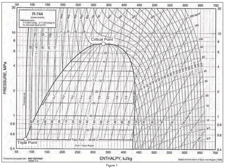
Figure 1 shows a Mollier diagram for carbon dioxide for pressures between 4BarA and 200BarA.
The basic figure was obtained from ASHRAE Handbook 2005, Fundamentals, but the critical point and the triple point have been emphasised because they are important to an understanding of the unique properties of carbon dioxide as a refrigerant.
The saturation pressure of carbon dioxide at 0°C is 34.85 Bar. This can be compared with the saturation pressure of ammonia at the same temperature which is 4.29 Bar.
Critical pressure and critical temperature of carbon dioxide are 73.7 Bar and 30.98°C. Critical pressure and critical temperature of ammonia are 113.3 Bar and 132.2°C.
As there is zero latent heat at the critical point, it is obvious that the relatively efficient Rankine cycle cannot operate at or above the critical temperature. Methods of improving cycle efficiency described in this paper depend on increasing the available latent heat of evaporation in the refrigeration cycle.
The critical temperature of 30.98°C is so low that it will be exceeded in many applications of refrigeration, though not necessarily all the year round.
Another point of interest is that the triple point of carbon dioxide is -56.57°C at a pressure of 5.18Bar. At the triple point, a substance is on the boundary between solid, liquid and vapour states. Any reduction in pressure will turn it into a solid. Carbon dioxide is unusual among refrigerants in that it cannot exist as liquid at atmospheric pressure. Most people Maximizing Efficiency of Carbon Dioxide Refrigerating Systems continued from page 6 will be familiar with solid carbon dioxide and with the effect of liquid carbon dioxide, sprayed into the atmosphere, turning into vapour and white powder.
Another feature of carbon dioxide is that it evaporates at well above atmospheric pressure throughout its operating range. This is a significant advantage compared to ammonia which evaporates at sub-atmospheric pressure at temperatures below -33.3°C.
Properties of carbon dioxide are significantly different from those of all other practical refrigerants.
It would be unwise to design carbon dioxide refrigerating systems based on experience of other refrigerating systems. It is advisable to go back to first principles.
Methods of Improving System Efficiency
As previously indicated, most methods of improving efficiency of carbon dioxide refrigerating systems depend on increasing the amount of latent heat of evaporation that can be used during the refrigeration cycle. There are several ways in which this can be done. Some of these ways can be combined to produce even greater improvements in efficiency.
Systems using carbon dioxide as a volatile secondary refrigerant
Carbon dioxide has very good heat transfer and transport properties and is therefore ideally suited for use as a volatile secondary refrigerant. A volatile secondary refrigerant system is one in which the circulating liquid refrigerant is allowed to extract heat by evaporating at more or less constant pressure before being drawn to a condenser where it is re-liquified without need for re-compression. Circulation may be by pump or by other means such as gravity.
Advantages include high coefficients of heat transfer, low mass flows relative to refrigerating duty and the simplicity of not requiring a compressor for the carbon dioxide. Such systems can be oil-free.
Condensation is usually well below critical temperature. Large amounts of latent heat are available.
It has been found that, when used in European supermarket systems, the system efficiency is comparable to, or even greater than, system efficiency of conventional direct expansion halo-carbon systems. Reasons for this surprising result include the small temperature differences at which carbon dioxide condensers and evaporators can operate, the significant pressure drops in halocarbon return lines of existing systems and the fact that more effective primary refrigerants, such as ammonia or propane, can be used.
Use of carbon dioxide as a volatile secondary refrigerant has proved to be practicable and efficient provided the evaporating temperature is not too low. The method could be applied to air conditioning and would be especially beneficial when using chilled ceilings.
However, the primary refrigerant must always evaporate at a temperature lower than the evaporating temperature of the carbon dioxide. This becomes a disadvantage at low evaporating temperatures, especially if the primary refrigerant is ammonia. At low evaporating temperatures it has been found better to use a cascade system.
Systems using carbon dioxide in cascade with another refrigerant
The first large modern carbon dioxide/ammonia refrigeration system was installed by Star Refrigeration Ltd in 1992 for Nestle at Hayes in Middlesex, England. The installation was for the freeze drying of coffee and produced several MW of refrigeration at temperatures below -50°C.
Cascade refrigerating systems using carbon dioxide and ammonia for the freeze drying of coffee have become the de-facto standard for this type of production worldwide.
Intermediate temperatures for such systems are well below the critical temperature of carbon dioxide. Large amounts of latent heat are thus available, leading to high system efficiencies.
Ammonia is an excellent refrigerant provided the evaporating temperature is not too low. However, at low evaporating temperatures, below, say, about -35°C, the specific volume of ammonia becomes very large and it is therefore necessary to employ large and expensive compressors with correspondingly large friction losses.
It is more economic in total system cost to use a carbon dioxide/ammonia cascade refrigerating system than a two stage ammonia system at evaporating temperatures lower than somewhere in the range between -30°C and -40°C, depending on the equipment being used and depending on the condensing temperature.
The carbon dioxide compressor would require about one eighth of the swept volume of an ammonia compressor to produce the same amount of refrigeration.
Cascade systems have been applied to low temperature cold stores, to blast freezers and to plate freezing systems with very good results.
It is relatively easy to apply carbon dioxide to large systems using either the volatile secondary method or the cascade method. However, even simpler systems are required for small to medium sized refrigerating systems.
Systems using only carbon dioxide
It is clear that air cooled systems using carbon dioxide will reject heat to atmosphere at temperatures above 31°C from time to time.
There is an optimum supercritical discharge pressure at which system efficiency is greater than at any other supercritical discharge pressure. It is not generally realised how low this efficiency is compared to system efficiency at most subcritical discharge pressures.
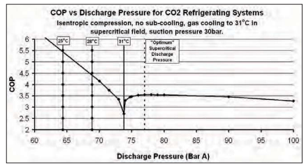
Figure 2 shows ideal COP for carbon dioxide refrigerating systems against discharge pressure in BarA.
It can be seen that, as the discharge pressure rises, COP falls to a minimum at about 74 BarA. However the COP rises sharply as the critical pressure is passed and reaches a maximum supercritical COP of just over 3.5 at about 77BarA under the conditions given. The “optimum” supercritical COP is much lower than the sub-critical COP at a condensing temperature of 28°C.
Year-round condensing temperatures of 28°C or lower can be achieved in many regions of the world by use of evaporative condensers. It is very desirable to avoid rejecting heat in the supercritical region if at all possible.
Whether or not a carbon dioxide refrigerating system is operating in a trans-critical cycle, it is always desirable to find ways of increasing the available latent heat of evaporation
Small fully sealed systems
Small single-stage carbon dioxide systems using hermetic and semi-hermetic compressors have been used for several years in drinks dispensers and other applications where it is desired to avoid use of halo-carbon refrigerants or their flammable replacements. Such systems are now proven in practice and produce system efficiencies comparable to efficiencies achieved in practice using halo-carbon refrigerants. However these efficiencies are very low compared to what is theoretically attainable.
Supermarket systems
Carbon dioxide systems of various types have come to dominate supermarket refrigeration in Northern Europe. In general, year-round system efficiencies are higher than system efficiencies for comparable halo-carbon refrigerant systems, though, in summer, the halocarbon systems are usually somewhat better.
Most supermarket refrigerating systems operate at two or more temperature levels. The high temperature levels use multiple, trans-critical semi-hermetic compressors rejecting heat to air- cooled gas coolers that function as condensers in cooler weather. In many instances the air for the gas coolers is cooled adiabatically by water spray during warm weather thus limiting power required for the compressors and improving efficiency.
The low temperature levels use sub-critical semihermetic carbon dioxide compressors rejecting heat to the high stage system either by cascade or directly to the high stage suction.
As yet there is no consensus as to the best type of system.
In many cases, system efficiency is improved by sub-cooling the high pressure carbon dioxide fluid in heat exchange with mains water that is heated to domestic hot water temperatures. This provides “free” hot water and improves performance of the refrigerating system.
Figure 3. shows that the output and the COP of a carbon dioxide system can be increased by 33% merely by using mains water to sub-cool the refrigerant to 15°C. The resultant hot water is cheaper than free!
Car air conditioning systems
The dominant refrigerant for car air-conditioning remains R134a, though it is scheduled for replacement by refrigerants with lower global warming potential.
Carbon dioxide is one such refrigerant though it has not yet found the world-wide acceptance that would be required in this market.
To be successful, carbon dioxide systems must become as reliable, as compact and as cheap as the well-established halo-carbon systems.
In the writer’s opinion, carbon dioxide systems for cars must be fully sealed, economised, two stage systems with electronic speed control powered from the car’s electrical system. Some early designers fell into the trap of copying what had been done before for halocarbon systems. It now seems obvious that high pressures associated with carbon dioxide militate against use of shaft seals and that the required variable refrigerating capacity of a sealed system is better performed by electronic speed control than by varying swept volume at constant speed.
Experience with supermarkets and with Eco-cute water heaters suggests that year-round performance of an economised two-stage carbon dioxide system should be able to match performance of single-stage halo-carbon systems.
Unfortunately it is not possible to apply the trick of sub-cooling using mains water in a car but significant improvements in efficiency can be made by using two stage compression with economising even though the pressure ratio might not require more than one stage for mechanical reasons.
It is also possible to use the method of parallel compression whereby a parallel system using the same refrigerant is used to sub-cool the main flow of high pressure refrigerant. The parallel compression system not only improves efficiency but it provides higher capacity than would have been achieved from the combined swept volume of the compressors used without sub-cooling by parallel compression.
The advent of the electric car will provide an opportunity for carbon dioxide systems because heat rejected from a carbon-dioxide system can be used to replace waste heat from the internal combustion engine that will have been replaced by a much more efficient electric motor. Carbon dioxide systems should be well placed to provide the heating and de-humidification that is required during winter months as well providing cooling in the summer.
Water heating systems
One of the great success stories in the application of carbon dioxide is the development of all-electric water heating in Japan using carbon dioxide in heat pumps.
Conditions in Japan, which has very little indigenous fuel resource, favour this type of heating but the development has been so successful that it will be applied all over the world even in energy rich countries.
The system, which has the generic name “Eco-cute” is a prime example of improving efficiency by using sub-cooling to increase available latent heat of evaporation.
Mains water is heated to domestic hot water temperatures in counter-flow heat exchange with supercritical carbon dioxide in a heat pump system where the heat source may be ambient air or waste water.
In general, no use is made of the refrigerating effect but several similar systems have been installed where the heat source is chilled water returning to the water-chiller of a conventional air-conditioning system. By this means use is made both of the refrigerating effect and of the heating effect.
Systems using evaporative condensers
There is no fundamental reason why evaporative condensers should not be designed for use with carbon dioxide refrigerating systems. This would have the advantage of allowing year-round sub-critical operation in many parts of the world. In addition, the mains water supply for evaporation and for blow-down could be used for sub-cooling with the benefits already described.
Unfortunately the amount of make-up water required is relatively small compared to the beneficial sub-cooling that could be provided from larger flows of water.
A system has been designed that uses an evaporative condenser in conjunction with a water heater to produce system efficiencies that are comparable with, or which exceed, efficiencies of conventional refrigerating systems.
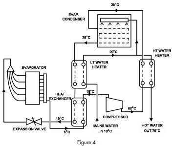
The circuit diagram is shown in figure 4.
The circuit includes a compressor, an evaporator, an evaporative condenser and three heat exchangers. Carbon dioxide is compressed to (say) 70 BarA and fed through a counter-flow, second stage, water heater to an evaporative condenser. In the condenser, the refrigerant is condensed to liquid at about 28°C. Liquid refrigerant leaves the condenser at about that temperature and passes through a first stage water heater before passing through a liquid to suction heat exchanger on its way to the expansion device. After the expansion device, the refrigerant extracts heat in the evaporator before returning to the compressor via the suction/ liquid heat exchanger.
Efficiency of the refrigerating system is improved by subcooling in two stages while maintaining a low discharge pressure by using an evaporative condenser.
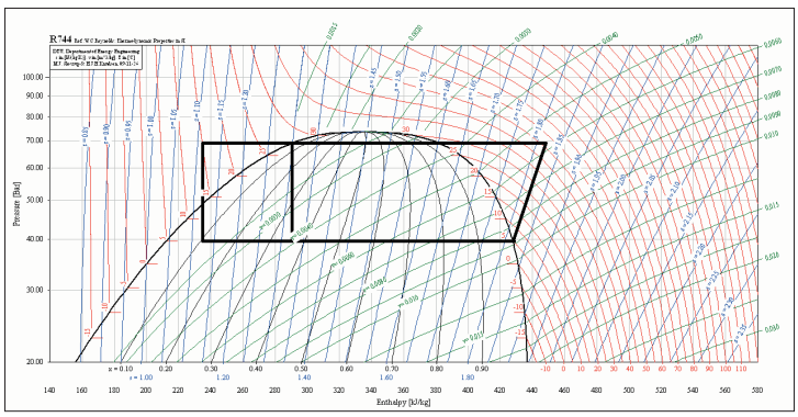
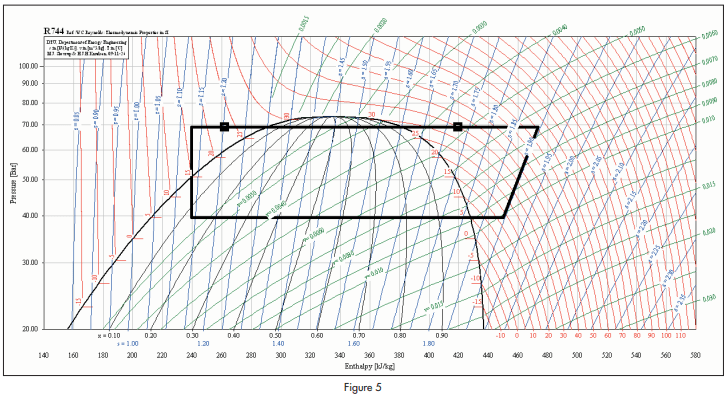
The proposed cycle is illustrated on a Mollier diagram shown in figure 5.
For a cycle as illustrated, where the evaporating temperature is +5°C and the condensing temperature is 28°C, the COP of the system as a refrigerator would be 5.31, assuming an isentropic efficiency of compression of 65%. The COP of the system as a water heater would be 2.05.
Operation of the system at lower evaporating temperatures would provide more hot water.
It is rather difficult to compare performance of a carbon dioxide system of this special type with conventional systems using R404A or R410A because assumptions have to be made about the operating conditions that would apply. Assumptions also have to be made about how compressors on the various refrigerants would perform under these operating conditions.
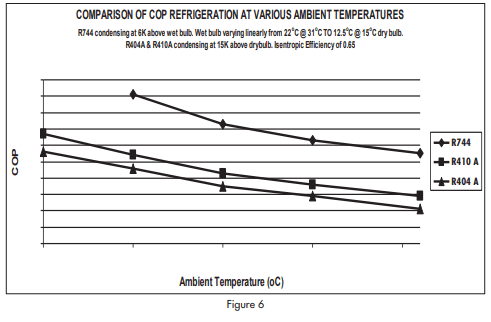
An active spread sheet was prepared for the system illustrated in figure 4 using manufacturer’s data. From this sheet it was possible to calculate COP (r) and COP(h) as well as temperatures and pressures round the system. It was assumed that the conventional systems on R404A and on R410A would use air cooled condensers and that the refrigerant would condense at 15K above ambient temperature. This is a relatively conservative assumption because air cooled systems are often designed to operate with much larger temperature differences.
It was assumed that relative humidity of the air varied linearly from 45% at 31°C (22°C wet bulb) to 75% at 15°C (12.5°C wet bulb). This is typical of temperate climates but is not representative of dry climates nor is it at all representative of tropical climates.
Figure 6 shows variation of compressor COP(r) in ambient temperatures ranging from 10°C to 31°C.
It can be seen that the special carbon dioxide refrigerating system is consistently more efficient than conventional air cooled systems on halo-carbon refrigerants even though the temperature difference of the air cooled system was restricted to 15K.
Pump and fan power are not included in the model. In general, fan powers for air cooled condensers would be greater than fan powers for equivalent evaporative condensers. The model is, therefore, not biased in favour of the evaporative condenser system.
Acknowledgements
I would like to thank Danish Technical University for use of their refrigerants program, Coolpak, that produced many of the diagrams and calculations for the paper.
Conclusions
- Carbon dioxide refrigerating systems are sufficiently different from conventional refrigeration systems to justify a return to first principles at design stage.
- The high pressures at which carbon dioxide systems operate provide benefits that outweigh any disadvantages.
- Efficiency of carbon dioxide systems can be increased to match efficiencies of conventional systems but only at cost of increased complexity.
- Trans-critical operation should be avoided if possible because it implies low efficiency except in the special case where water can usefully be heated from mains temperature to high temperature.
- All valid methods of improving efficiency of carbon dioxide refrigerating systems depend on increasing the latent heat available for evaporation.
- A system has been designed that allows carbon dioxide systems to be operated at efficiencies that exceed efficiencies of conventional air cooled systems
Correction…..
A story by Forbes Pearson, entitled “Further Improvements in Ammonia Low-Pressure Receiver Systems,” which appeared in the November 2012 issue of the Condenser, erroneously referred to “Figure 7” when describing “remote print-out of site readings.”
Instead of referencing this illustration as “Figure 7,” the text should have referenced “Figure 8,” which was left out of the paper entirely. This may have puzzled some readers.
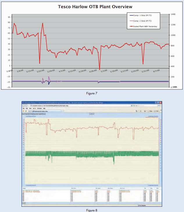
Remote monitoring and recording of system performance is a very valuable tool and is not now prohibitively expensive. There is almost no limit to the amount of data that can be recorded and transmitted almost instantaneously.
Two figures that illustrate this idea and were left out of the original publication of this paper appear below.


