CO2 EVAPORATOR DESIGN
Editor’s Note
The process of selecting air cooling evaporators to operate in a CO2 refrigeration system is very similar to selecting evaporators for ammonia. Evaporator manufacturers typically require the same input data for both refrigerants and likewise display performance and selection data in the same way.In this technical paper, author Bruce Nelson outlines the ways that CO2 evaporators and ammonia evaporators differ.
While they are similar in that both have tubes, fins, and fans, CO2 evaporators are very different in a number of respects which are important for refrigeration designers and operating engineers to understand.
In the following paper, the author addresses subjects including general use, material compatibility, pressure, heat transfer, the effects of oil in evaporators, the optimum overfeed rate for pumped CO2 , direct expansion with CO2 and defrost.
Bruce I. Nelson, P.E., President, Colmac Coil Manufacturing, Inc.
INTRODUCTION
The process of selecting air cooling evaporators to operate in a CO2 refrigeration system is very similar to selecting evaporators for ammonia. Evaporator manufacturers typically require the same input data for both refrigerants and likewise display performance and selection data in the same way.
Typically, the following inputs are required for properly selecting either CO2 or ammonia evaporators:
- Elevation
- Return air (‘Air on’) temperature
- Return air relative humidity
- Evaporating temperature
- Type of feed
- Overfeed rate (if pumped feed)
- Liquid pressure and temperature at the expansion valve (if DX)
- Required cooling duty
- Type of defrost
- Supply voltage
- Materials of construction
- Required MAWP (Maximum Allowable Working Pressure)
Other inputs may include:
- Maximum allowable air velocity
- Minimum air flow rate
- Maximum allowable fan speed
- Maximum allowable sound pressure (usually in dB(A))
- Minimum air throw distance
- Minimum number of fans
- Dimensional constraints (maximum height or length limitations)
Output data typically includes:
- Actual cooling duty
- Air flow rate and air velocity
- Leaving air temperature
- Leaving air relative humidity
- Sound pressure level
- Air throw distance
- Dimensional characteristics
-
- Cabinet H x W x L
- Weights
- Internal volume
aa. Electrical characteristics
-
- Number of fans/motors
- Fan speed
- Fan motor brake power
- Full load amperage and/ or power consumption
To the uninitiated, the above may imply that CO2 evaporators and ammonia evaporators are interchangeable and essentially the same animal. While they are similar in that both have tubes, fi ns, and fans, CO2 evaporators are very different in a number of respects which are important for refrigeration designers and operating engineers to understand. Highlighting and quantifying these differences is the subject of this handbook chapter.
GENERAL
Most commonly used feed methods for CO2 are:
- Pumped liquid
- Direct expansion
While gravity flooded feed is very effective with ammonia, it is not commonly used with CO2 due to:
The higher density of CO2 liquid compared to ammonia. This higher density results in elevated evaporating temperatures in the evaporator due to liquid head in the surge drum and drop leg.
The higher pressure rating required for the surge drum.
Poor performance due to necessarily low pressure drop (equal to the available head of liquid in the surge drum drop leg). This reduces allowable mass flux and results in low boiling heat transfer coefficients.
Most ammonia evaporators are defrosted by air, water, or hot gas. Electric defrost is not commonly used due to the flammability characteristics of ammonia. This is because electric defrost elements typically have high surface temperatures and are necessarily placed in close proximity to coil tubes.
CO2 , on the other hand, is commonly defrosted by air, water, and electric resistance heating. However, hot gas defrosting is uncommon because of the high gas pressures required. Electric defrost is very effective and is widely used with CO2 due to its simplicity and low first cost.
As explained above there are many similarities in evaporator rating methods and construction, however, the very different thermodynamic and chemical characteristics of CO2 compared to ammonia require special attention with regard to:
- Material Compatibility. Unlike ammonia, CO2 can be used safely with copper and copper-bearing alloys. Actually, dry CO2 is quite inert and can be used with all commonly used base metals; copper, carbon steel, stainless steel, and aluminum. Care must be taken to select materials with sufficient strength to withstand the higher MAWP required for CO2 . This normally rules out the use of aluminum with CO2 .
- Pressure. CO2 pressures are much higher than ammonia.
- Heat Transfer. Thermodynamic and transport properties are very different for CO2 compared to ammonia and result in very different evaporator circuiting arrangements to achieve equivalent cooling capacity.
MATERIAL COMPATIBILITY
For many years, ammonia evaporators were made of carbon steel tubes and fi ns hot dip galvanized after fabrication. While this type of construction is corrosion resistant and has sufficient strength to perform well in most ammonia refrigeration systems, carbon steel is not an ideal material to use with carbon dioxide for two reasons:
- Tubeside Corrosion. If there is any residual water present in the piping or vessels of a carbon dioxide system on startup, it can combine with the carbon dioxide to form carbonic acid. Carbon steel is susceptible to corrosion when exposed to even mildly acidic solutions.
- Embrittlement at Low Temperatures. Carbon steel is known to become brittle at temperatures below about -20 deg F. Even though the strength of the metal increases as the temperature is reduced, even low carbon steel will become embrittled and prone to fracture when subjected to impact loading. One of the advantages of CO2 is the improved cycle efficiency (reduced power consumption) at very low (blast freezing) temperatures. Low temperature operation with carbon steel evaporators is problematic for this reason and not recommended.
Aluminum is an excellent metal to use in evaporators for several reasons (Nelson 2012) and so is in wide use in industrial ammonia refrigeration systems. While the yield and tensile strength of this metal are sufficient to easily handle ammonia pressures, they are generally not high enough to achieve the higher design pressures needed for carbon dioxide. Aluminum is therefore not recommended for use with carbon dioxide.
Copper, unlike carbon steel, does not suffer embrittlement at low temperatures. It resists corrosion when exposed to mild acids and so can stand exposure to low concentrations of carbonic acid. Because of the possibility of exposure of the brazed joints to carbonic acid, it is highly recommended that copper tube evaporators be brazed using a non-phosphorous bearing alloy filler metal. The yield and tensile strengths of copper are high enough to reach required design pressures for freezer temperatures, but in rooms above about 0 deg F the required design pressures become higher than can be practically achieved with copper tubes. Therefore, copper tube construction is considered appropriate for carbon dioxide evaporators installed in rooms 0 deg F and colder.
Stainless steel is an ideal tube material for use in carbon dioxide evaporators because of its high yield and tensile strength and corrosion resistance. Also, like aluminum and copper, stainless steel is not susceptible to embrittlement even at extremely low (cryogenic) temperatures.
Conclusions:
Material Compatibility
- Both copper and stainless steel tubbing and pipe are recommended for use in CO2 evaporators provided the diameters and wall thicknesses meet the required design pressures.
- When using copper, a non-phosphorous bearing brazing alloy is recommended. This is needed to limit the risk of leaks caused by acidic conditions resulting from the presence of carbonic acid.
- Carbon steel is not recommended for use in CO2 evaporators due to a) susceptibility to corrosion in the presence of carbonic acid, and b) embrittlement at low temperatures (lower than -20 deg F).
- Aluminium is not recommended for use in CO2 evaporators due to its lower yield and tensile strength characteristics.
PRESSURE
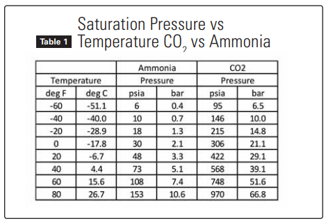
Table 1 below compares the saturation pressures for CO2 and ammonia and illustrates the significantly higher pressures (and consequently higher strength requirements) for CO2 .
ASHRAE Standard 15 “Safety Standard for Refrigeration Systems”, sets the minimum design pressure for evaporators in Section 9.2.1. This section of the standard also refers to the ASME Boiler and Pressure Vessel Code, Section VIII, as the appropriate method of determining the design (or ‘working’) pressure given evaporator dimensions and materials of construction.
Section 9.2.1 sets up design pressure criteria for various types of refrigeration systems and states that “…Design pressure for mechanical refrigeration systems shall not be less than 15 psig and, except as noted in Sections… 9.2.6, shall not be less than the saturation pressure corresponding to the following temperatures: a.) Lowsides of all systems: 80 deg F (26.7 deg C).” From Table 1, for CO2 the design pressure corresponding to 80 deg F is 969.6 psia (66.8 bar), or 955 psig. Section 9.2.2 states “The design pressure for either the highside or lowside need not exceed the critical pressure of the refrigerant unless such pressure are anticipated during operating, standby, or shipping conditions.” Critical pressure for CO2 is 1070 psia (73.8 bar), or 1055 psig.
Section 9.2.6 (9.2.1 above) describes specific exceptions when carbon dioxide is the refrigerant, as follows: “
When a refrigerating system utilizes carbon dioxide (R744) as a heat transfer fluid, the minimum design pressure for system components shall comply with the following.
9.2.6.1 In a circuit without a compressor, the design pressure shall be at least 20% higher than the saturation pressure corresponding to the warmest location in the circuit.
9.2.6.2 In a cascade refrigerating system, the highside design pressure shall be at least 20% higher than the maximum pressure developed by a pressure-imposing element, and the lowside pressure shall be at least 20% higher than the saturation pressure corresponding to the warmest location in the circuit.”
The intent (as understood by the author) of the phrase “warmest location in the circuit” is to mean the room temperature in which the evaporator(s) will operate. For example, a CO2 evaporator in a cascade refrigerating system is being designed to operate in a 0 deg F room. From Table 1 the saturation pressure corresponding to 0 deg F is 305.7 psia. Minimum required design pressure according to Section 9.2.6.2 would then be 305.7 x 1.2 = 366.8 psia = 352 psig.
Table 2 shows the calculated minimum required design pressure for CO2 evaporators according to Section 9.2.6.
Knowing the required minimum design pressure from the above now allows us to determine tubing diameter and wall thickness according to the calculation method shown in the ASME Boiler and Pressure Vessel Code, Section VIII. Material properties used in the calculations are taken from ASME Section II.

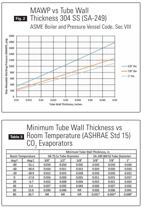
Since copper and stainless steel are recommended for use in carbon dioxide evaporators (see above), Figures 1 and 2 below have been constructed to show the calculated Maximum Allowable Working Pressure (MAWP) for commonly used tube diameters over a range of wall thicknesses.
Using data from Table 2 with Figures 1 and 2 allows the required tubing wall thickness to be calculated for different tubing diameters and materials given the room temperature.
Table 3 shows the tube wall thickness needed to meet the requirements of ASHRAE Standard 15 in a CO2 evaporator operating at various room temperatures.
Note that the minimum tube wall thicknesses shown in Table 3 are theoretical calculated values. In normal manufacturing practice, copper tubing with wall thickness less than about 0.016” is difficult to produce and to handle. With stainless steel tubing the practical minimum wall thickness is around 0.020”.
Bear in mind that Table 3 applies only to evaporator tubes, not to headers or piping connections. The evaporator manufacturer must also properly design coil headers and piping connections according to ASME Section VIII to have MAWP equal to or greater than the tubing MAWP.
While lower temperatures may allow the use of light wall tubing and relatively low design pressures during normal operation, the system designer must remember that the design pressure must be selected to accommodate all potential temperature/pressure conditions including (but not limited to):
- Startup conditions
- Peak load operation
- Abnormal loads (process temperature excursions)
- Standby conditions that occur frequently
ii. Power outages limited in time duration but which may happen with some frequencyii. Shutdown during cleanup
Conclusions: Pressure
- CO2 evaporators will operate at significantly higher pressures than ammonia for a given temperature.
- In the United States, ASHARE Standard 15 establishes design pressure requirements for CO2 systems.
- ASHARE Standard 15 requires the design pressure for CO2 evaporators to be “…at least 20% higher than the saturation pressure corresponding to the warmest location in the circuit.” The “warmest location in the circuit” is interpreted as the warmest anticipated room temperature in which the evaporator(s) will operate.
- Minimum recommended tube wall thicknesses are shown in Table 3, however, the evaporator manufacturer must insure that all pressure bearing components in the coil, including headers and pipe connections, are designed correctly.
- The temperature used to establish design pressure must be carefully selected to account for conditions which include (but are not necessarily limited to) those shown below:
-
- Startup conditions
- Peak load operation
- Abnormal loads (process temperature excursions)
- Standby conditions that occur frequently
- Power outages limited in time duration but which may happen with some frequency
- Shutdown during cleanup
HEAT TRANSFER
The driving potential for heat transfer in an air cooling evaporator is the mean temperature difference between the air and the boiling refrigerant. Frictional pressure drop on the tubeside of the evaporator reduces the mean temperature difference and therefore the cooling capacity of the evaporator. This coupling of fluid flow (frictional pressure drop) and heat transfer is unique to evaporators. As refrigerant mass flux increases; a) the heat transfer coefficient increases which increases cooling capacity, but b) pressure drop also increases which reduces cooling capacity. Evaporator manufacturers optimize this balance of heat transfer with pressure drop by adjusting the number of feeds and passes for a given coil geometry and operating conditions.
Boiling heat transfer in tubes has been studied for several decades with continual improvement to correlations and accuracy of the predictions. The convective boiling heat transfer coefficient is a strong function of refrigerant mass flux (also called mass velocity), viscosity, and the ratio of liquid to vapor densities. It is a weaker function of thermal conductivity and specific heat. The combination of these properties actually favor ammonia, which produces significantly higher (200% to 300%) boiling heat transfer coefficients when compared to CO2 at the same mass flux.
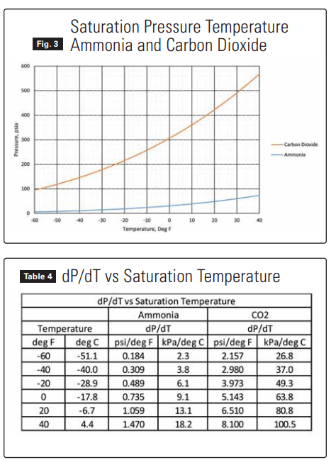
The good news with CO2 is the much steeper slope of the vapor pressure curve compared to ammonia, shown in Figure 3 below. This relatively steep slope (dP/dT) means that CO2 evaporator circuiting can be designed for higher mass flux without the pressure drop penalty seen with ammonia. The higher design mass flux with CO2 offsets the lower boiling heat transfer coefficient compared to ammonia and results in evaporator performance which is very nearly equivalent.
The slope of the vapor pressure curve in Figure 3 has been tabulated in Table 4 and illustrates the difference between pressure drops seen in ammonia versus CO2 evaporators. Typically evaporator manufacturers will design evaporator circuiting to limit tubeside pressure drop to a value corresponding to approximately 1.8 deg F (1.0 deg K) change in evaporating temperature. Using the slope of the vapor pressure curve (dP/dT) shown in Table 4, at -20 deg F saturated suction temperature, a 1.8 deg F change in evaporating temperature corresponds to a pressure drop of 1.8 x 0.489 = 0.88 psi for ammonia, and 1.8 x 3.973 = 7.15 psi for CO2 . As explained earlier, this higher allowable pressure drop with CO2 means that evaporator circuiting can be arranged for fewer feeds and more passes (longer circuit length) compared to ammonia. Again, when designed properly by the manufacturer, similar sized evaporators will produce cooling capacity with CO2 which is equivalent to ammonia.
Conclusions: Heat Transfer
- CO2 evaporators should be designed for higher mass flux and pressure drops than ammonia evaporators due to the much larger dP/dT characteristic of CO2 . This appears as longer circuit lengths for CO2 compared to ammonia.
- If circuited properly, an evaporator operated with CO2 will have equivalent cooling capacity to an evaporator of the same dimensions operated with ammonia. i.e. CO2 does not penalize performance in evaporators compared to ammonia.
EFFECTS OF OIL IN EVAPORATORS
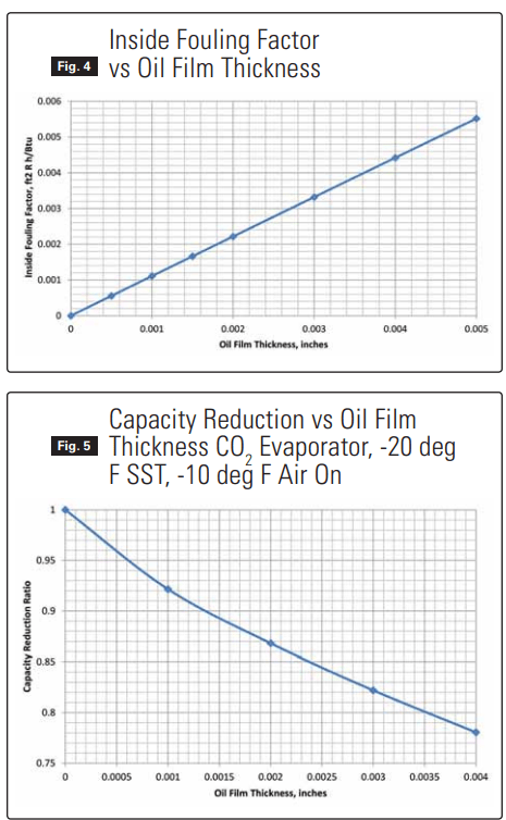
Industrial CO2 refrigeration systems typically use immiscible oil for compressor lubrication. Unless effectively removed from the CO2 discharge gas in the oil separator, some amount of oil is likely to reach evaporators and coat internal tube surfaces. The effect of this oil coating can be quantified in the form of a fouling factor, which is added to the overall resistance to heat transfer of the evaporator surface. Figure 4 below shows the calculated fouling factor for increasing oil film thickness in evaporator tubes.
Figure 5 translates this fouling factor into an expected reduction in cooling capacity for a CO2 evaporator operated with increasing oil film thickness. For example, a CO2 evaporator design to operate oil-free will have its cooling capacity reduced by a factor of 0.87 (a 13% reduction) when the internal tube surfaces are coated with an oil film 0.002” thick.
Conclusions: Effect of Oil on Heat Transfer
- If immiscible compressor oil is allowed to coat internal tube surfaces in CO2 evaporators, cooling capacity will be reduced.
- Installation of a high efficiency oil separator to minimize the amount of oil reaching evaporators is recommended.
OPTIMUM OVERFEED RATE FOR PUMPED CO2
Reducing the overfeed rate in pumped refrigerant systems is desirable because pumping power will be reduced by the cube of the ratio of the reduction in flowrate. As the liquid overfeed rate is reduced, however, the risk of operating evaporators with the refrigerant in separated flow patterns (stratified/wavy) increases. Cooling capacity of the evaporator falls off dramatically when this occurs. With CO2 in an evaporator having 5/8” tubes, a minimum mass flux of 200 kg/m2-s is required to avoid stratified/ wavy flow.
The thermodynamic properties of CO2 differ significantly from ammonia:
- Latent heat of vaporization is much lower resulting in higher mass flow rates for a given cooling capacity.
- The ratio of liquid to vapor density is much lower which results in lower void fractions (less tube volume occupied by vapor).
- Higher mass flux for reasons explained above (see Heat Transfer section).
These characteristics allow pumped CO2 evaporators to be designed for lower overfeed rates compared to ammonia. Recommended overfeed rates for pumped CO2 evaporators are 1.5:1 for coolers and 2:1 for freezers. In comparison, to avoid separated flow in pumped ammonia evaporators, recommended overfeed rates are 3:1 for coolers and 4:1 for freezers.
Conclusions: Optimum Overfeed Rate
- Pumped CO2 systems can be successfully operated with lower overfeed rates compared to ammonia.
- Recommended overfeed rates for pumped CO2 evaporators are 1.5:1 for coolers and 2:1 for freezers.
DIRECT EXPANSION WITH CO2
CO2 evaporators can be operated with direct expansion feed. Care must be taken by the evaporator manufacturer to circuit the coil in such a way that the refrigerant mass flux is kept above 200 kg/m2-s in order to avoid stratified/wavy flow. This becomes challenging with larger diameter tubes (greater than 5/8”). At very low temperatures, enhanced tubes (microfin copper) are recommended as a way to mitigate separated flow patterns and improve performance.
DEFROST
CO2 evaporators are commonly defrosted using the following methods:
- Air
- Water
- Electric resistance
Control valve groups for these methods of defrost are very simple and low cost.
Hot gas defrost with CO2 evaporators is not commonly used. In a cascade system, the intermediate CO2 temperature/pressure is normally too low to allow the CO2 from that circuit to be used for defrost. This then requires a separate high pressure (capable of 50 bar) compressor with sufficient capacity to be installed expressly for purposes of providing hot gas for defrost. Other means of generating hot CO2 gas for defrost include use of a heat-driven boiler vessel, typically heated by discharge gas from the high side of the cascade system. The complexity and added expense of hot gas defrost with CO2 has limited its application.
BIBLIOGRAPHY
ASHARE (2013). ANSI/ASHARE Standard 15-2013. Safety Standard for Refrigeration Systems”. American Society of Heating Refrigerating and Air-Conditioning Engineers. Atlanta, GA
ASME Boiler and Pressure Vessel Code, Section VIII.American Society of Mechanical Engineers. New York, NY
Nelson, B.I., 2012 “Comparing Ammonia Evaporator Construction: “Which one is best?”. Colville, WA.