ASME Low Temperature Requirements for Impact Testing
RICHARD MERRILL
For those of us that didn’t major in metallurgy, steel was always a pretty simple material. It was pretty springy and flexible stuff. Just about any shape was possible. Steel could be loaded up to a point and it would bend, but when unloaded it would spring back to its original shape. If we loaded it a little further, it would flex further, but when unloaded, it would spring back a little but not all the way. It had taken a permanent set. We call it a permanent set, but it can usually be loaded in the other direction to restore it to nearly the original shape and condition. Just don’t flex it too many times or it might break due to fatigue failure.One of the nice things about most steels is that they will yield a significant amount before they fail under tension. Yielding provides a bit of safety before failure. This nice quality is known as “ductility”. That is the ability of the material to yield before it breaks. Metallurgists measure the point of yield and quantity of yield in various materials to categorize them. However, carbon steel is not always a simple material. In refrigeration pressure piping and vessels, ductility becomes a very important characteristic that we need to pay attention to, especially at low temperatures. At refrigeration and freezing temperatures, the ductility of carbon steel can diminish, and the metal can become brittle. Under stress, the metal can fracture with very little warning.
In WWII the might of American industry was a major factor in winning the war. One of our most notable products were the cargo ships known as Liberty Ships. During the war, over 2700 were built in 18 US shipyards. In 1943, the US launched three ships per day. Design was simple, materials were inexpensive, and construction was speedy. The carbon steel loss of ductility was soon experienced during the winter when ships were crossing the North Atlantic Ocean. About 1500 ships experienced serious cracks in their hulls and decks. Twelve ships broke in half and sunk. Designs were modified but the Liberty Ships were never quite safe in the cold.
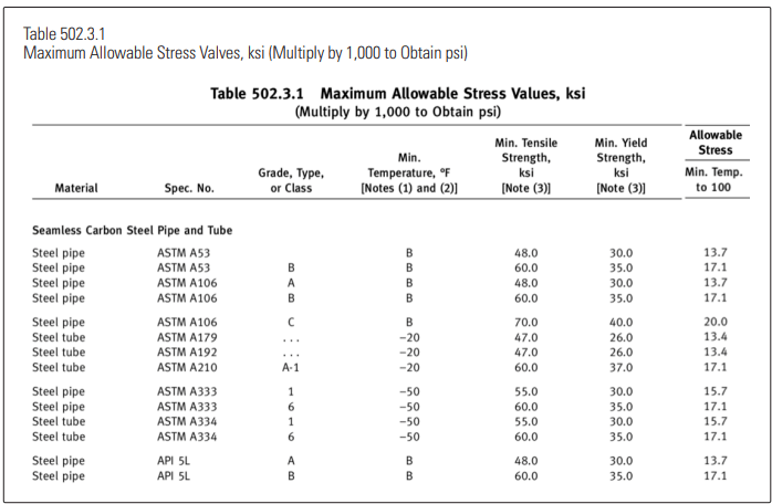
We find ourselves, 70 years later using much the same carbon steel for our pressure vessels and pressure piping at lower and lower system design temperatures. The two controlling codes, ASME Section VIII for vessels and ASME B31.5 for piping, have recognized the problem and have methods for dealing with the loss of ductility at low temperatures. Both codes are under the control of the ASME and use common allowable stress tables for carbon steel plate and pipe and, mostly, common stress calculation methods. See Table 502.3.1.
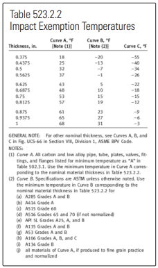
Different specification materials experience a loss in ductility at different temperatures. In the allowable stress tables, minimum allowable temperatures are specified. For some materials it is specified as simply a temperature (i.e. -20°F) and for other materials the user is sent to a table of values (i.e. Curves A, B and C in Table 523.2.2) where the minimum temperature is a function of metal thickness. Thinner materials are less likely to experience brittle fracture due to lower internal stresses. The thinner materials have lower minimum temperatures specified in the charts. If your system lowside design temperature is warmer than the material minimum temperature, brittle fracture is not going to be a problem. If your lowside design temperature is below the material minimum temperature, there is more work to be done.
Allowable stresses for most of the listed materials we are using are based on the tensile strength of the specific material. ASME takes that tensile strength and divides it by 3.50. It is often referred to as a “safety factor” but ASME prefers not to call it that.
For other materials that have no ductility at any temperature, such as cast iron, they divide the tensile strength by a factor of 10. A lot more safety than the 3.5 factor.
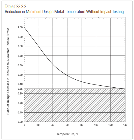
ASME B31.5 has rules governing refrigerant piping of all types (not just ammonia). B31.5 follows the rules and conventions of ASME Section VIII but in several areas, it simplifies those rules and lists fewer material choices than listed in the Boiler and Pressure Vessel Code. In cases where B31.5 simplified the rules, they were always more conservative. A good example of this conservatism is the low temperature rules. Prior to around 2001 if the design temperature went below the minimum allowed metal temperature, the safety factor immediately went to 10. If you can maintain stresses below the “safety factor of 10” you should be able to avoid impact tested materials. One trick to keep the stresses low is to specify thicker materials or higher pipe schedules or different materials. In practice, B31.5 works like this: Paragraph 523.2.2, simply stated, tells us when the metal temperatures go below the material allowed minimum, allowed stress from Table 502.3.1, it gets multiplied by 0.35. Multiplying that “room temperature” allowable stress by 0.35 results in an allowable stress that is one tenth of the material tensile strength. (1/3.5 x 0.35 = 1/10). If your design stresses are below that number, you are exempt from impact testing requirements.
However, this is a pretty severe and abrupt penalty. If you slip from a -20°F to a -21°F design temperature, you have an instant derate by 65%. But the ASME Boiler and Pressure Vessel Code, Section VIII, UCS-66 has its own rules for calculating allowable stress in carbon steel used in a cold vessel. It has a sliding scale stress derate. The lower the temperature, the greater the derate on the allowable stress. Dropping from -20°F to -21°F is no problem.
Back in the early 90’s there were a number of complaints and requests to unify the two codes. Vessel manufacturers were building vessels with piping connections with a lesser wall thickness than the thickness required by the piping code. The resultant mismatch caused extra work for internal beveling of the thicker pipe and extra steps of inspection during fit-up. And it also caused extra material costs.
B31.5 did the work and got it through the ASME bureaucracy for the 2001 Edition. And in 2006 the language of paragraph 523.2.2 was clarified to make it clear that either method: the “safety factor = 10” method or the “temperature reduction curve” method from Section VIII were available to the designer.
The temperature reduction method isn’t as bad as it looks.
Figure 523.2.2 shows both methods. The left side asks you to divide your calculated design stress by the room temperature allowable stress for your material (from Table 502.3.1). If you enter the chart at 0.35 or below (in the shaded area) you are good for just about any low temperature. The scale across the bottom of the chart tells you how many degrees you can go below your material specified minimum temperature from 502.3.1. If you enter the chart above the 0.35 number, you traverse over to the curve. Then if you go down from there it tells you the temperature reduction from the minimum that you are allowed for your selected material.
If you’ve gotten this far and all is well, you won’t need to use impact tested material. Congratulations. If not, B31.5 paragraph 523.2.2 is titled “Impact Tests” but it has a rather incomplete description of the impact testing procedure as described in Section VIII, UG-84. This is better left to the metallurgical test labs used by your material supplier.
However, all is not lost. There are other solutions to the brittle fracture problem, all spelled out in paragraph 523.2.2. For example, carbon steel that is thinner than 0.10 inches is exempted down to -55°F. There are pipe specifications that include impact testing, such as A333, Grades 1 and 6 certified down to -50°F and some other grades are certified down to -150°F. Some aluminum and stainless-steel specs are totally resistant to low temperature embrittlement… good to -425°F.
One last point: While the hoop stress in a piece of pipe is very easy to calculate, there is much more to be considered. B31.5 requires that we consider stresses in the pipes due to weight loads, wind, seismic, vibration and thermal expansion or contraction. Paragraphs 519, 520 and 521 discuss the calculation of these extra loads. With anything more than a simple run of pipe, the B31.5 methods get very complex. Numerous software developers have software packages that do a much better job evaluating piping networks. It seems that ASME has deferred to these software packages for these problems. Regardless, all the other stresses must all be considered in the design, especially at low temperatures. It is most important to adequately support your piping such that it is protected from external loads and to be sure the piping is unconstrained with respect to thermal expansion and contraction.