ARF Safety Relief Research Project
Background
Pressure relief valves are engineered safety devices intended to protect pressure vessels and other pressurecontaining equipment from catastrophic failure as a result of excessive pressure excursions that may occur during operation or standby conditions. Requirements for the application of pressure relief devices for pressure vessels originate from the ASME Boiler and Pressure Vessel code (Section VIII Div. 1 UG 125). Both IIAR 2 and ASHRAE 15 have specific engineering requirements for sizing of both pressure relief valves as well as relief vent piping systems. Section 6.6.3 of IIAR Bulletin 110 provides guidance for the interval of replacement or recertification of pressure relief valves. Although most end users simply replace their pressure relief valves on a five (5) year interval as identified in Bulletin 110, some are considering the use ofan alternate provision for determining a performance-based interval for relief valve replacement. The following is one option for modifying the five (5) year replacement interval provided in Bulletin 110:
“An alternative to the prescriptive replacement interval, i.e., five years, can be developed based on documented in-service relief valve life for specific applications using industry accepted good practices of relief valve evaluation”
IIAR has developed a pressure relief valve test procedure to support this alternative interval for replacement. The test procedure includes a design and materials specification for a test rig suitable for use in collecting postmortem data from relief valves removed from service at the termination of their Ammonia Refrigeration Foundation UPDATE operating life. The rig design and test procedure are intended for use by endusers (or their contactors) who seek to modify their interval for replacement.
Relief Valve Test Rig
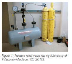
In the fall of 2008, the IIAR relief valve task force completed its development of a draft relief valve bench test procedure, including details on a relief valve bench test rig. In the fall of 2009, the IIAR Ammonia Refrigeration Foundation (ARF) funded the Industrial Refrigeration Consortium (IRC) at the University of WisconsinMadison to construct the proposed bench test rig, verify the rig’s function and the relief valve test procedure.
At the 2010 IIAR Annual Conference in San Diego, Todd Jekel and Doug Reindl of the IRC reported on the results of the relief valve bench test project. The researchers completed the construction of the relief valve bench test rig earlier this year and have been testing relief valves with varying set pressures, capacities, and connections sizes to assess the fitness of the test rig for functional testing and to validate the test procedure. The rig uses high pressure compressed air cylinders as the source for relief valve testing. Air from the compressed air cylinders is fed into 6.6 ft3 (0.19 m3) vessel. The vessel provides a buffer to feed air to the inlet of the relief valve being tested. The relief valve being tested is attached to the vessel by a 1-1/2″ (38 mm) connection. A full port ball valve is used to isolate the relief valve for removal without discharging the entire volume of the buffer vessel. A high accuracy bourdon tube pressure gauge sits immediately upstream of the relief valve inlet.
In order to verify the function of the test rig and corresponding procedure, the IRC researchers tested both newly manufactured and used relief valves. The table below shows combinations of valve capacity and set pressure that were tested to validate the bench test rig operation.
Preliminary Results
The researchers found that the test rig performed satisfactorily over the entire range of set pressures and capacities. They also confirmed that the pressure vessel feeding air to the pressure relief valve inlet was necessary to enable “pop testing” the relief valves. The vessel also served as a buffer to allow pressure relief valve blowdown to be observed and measured if needed.
The researchers recommended that the relief valve’s pop pressure be used as the primary criteria for valve function (e.g. pass/fail). The rig was not designed nor was the test procedure intended to measure valve capacity (lb/min). During the conference, the researchers showed a series of videos to demonstrate the rig operation. The researchers are completing revisions to the relief valve test procedure. Additional details on the results from this project will be available as a technical paper to be presented at next year’s IIAR annual meeting.
Acknowledgements
The researchers would like to gratefully acknowledge and thank a number of key stakeholders involved with this project – without which, it would not have been possible. Funding and project oversight was provided by the Ammonia Refrigeration Foundation (ARF) and IIAR Research Committee, respectively. Additional generous donations were provided by a number of other companies including:
- 500 psig vessel were provided by Isotherm, Inc.
- High pressure piping, fittings, and construction of the rig was provided by Rhode Brothers
- Newly manufactured pressure relief valves were provided by Hansen Technologies and Refrigerating Specialties
- Used pressure relief valves were provided by Kraft Foods/Oscar Mayer, and Schoep’s Ice Cream


