A Service Call In Space
by Liz Milner
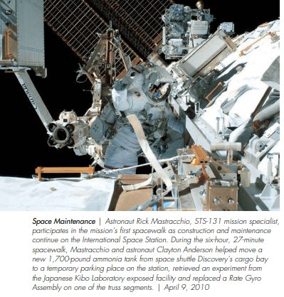
Ammonia took center stage recently in televised images of NASA astronauts attaching a 1700 lb, doublechamber tank which contained a 600 lb ammonia charge to the International Space Station (ISS). During the seven-hour-and-26- minute spacewalk, astronauts RickMastracchio and Clayton Anderson removed a depleted ammonia tank from the International Space Station and replaced it with a new one. Despite problems with some stuck bolts that caused an hour-and-ahalf delay, the astronauts were able to complete the tank change-out and also install two radiator grapple fixture stowage beams that will be used in the event that a radiator in the Space Station’s climate control system has to be replaced.
Two days later, a follow-up space walk to connect the new tank’s fluid lines so that it would become a fully functioning part of the Space station’s cooling system met with disappointment. As flight controllers began activating the tank to join it with the space station’s cooling system, a valve stuck. The trouble was with a nitrogen tank, which is needed to provide pressure to the ammonia loops that cool the exterior of the Space Station. The valve remained frozen in place despite the team’s best efforts. Since the Space Station has a redundant system that is functional, NASA engineers decided to leave the ammonia tank for the present and to fix the problem in a future mission.
The ammonia tank was replaced in one of the final stages of the International Space Station’s construction. The Space Station was assembled incrementally. As the new modules were added to the system, ammonia was diverted from the tank to fill the ammonia lines associated with these new modules. Redundancy was also built into the system, so there are two Ammonia Tank Assemblies (ATAs) at either end of the Space Station. Each ATA consists of a dual chambered tank, so there is a total of four chambers with a charge of 300 lbs each. In addition, there are four Photovoltaic Thermal Control Systems that have a fixed ammonia charge of 52 lbs each. The Photovoltaic Thermal Control Systems rely on the ATA for ammonia refills.
The International Space Station could not exist without its cooling system. Cooling is not just for keeping the astronauts comfortable, but also for insuring that computers and other delicate electronic systems are protected from being alternately frozen and overheated. “Without thermal controls,” a NASA publication says, “the temperature of the orbiting Space Station’s sun-facing side would soar to 250°F (121°C), while thermometers on the dark side would plunge to –250°F (–157°C).” Given this volatile environment, it is no wonder that ammonia, with its high thermal capacity and wide range of operating temperatures, was selected as the refrigerant for key components of the Space Station’s thermal control system. But ammonia’s advantages don’t stop there. Ammonia is also readily available and inexpensive. Even in outer space where ammonia’s environmentally friendly characteristics do not matter; its advantages still exceed those of synthetic refrigerants such as Freon. Because ammonia refrigeration is a relatively mature industry, there is a knowledge base on how to handle it safely—even in deep space!
Boeing is the prime contractor for the ISS’s ammonia cooling system and ammonia was selected as the refrigerant for the Space Station’s external cooling system because, in the words of Boeing Active Thermal Control System (ATCS) Analysis & Integration engineer, Thang Mai, it is simply “the best…it’s more efficient and has great viscosity which means liquid ammonia can travel through piping with minimum pumping power. This translates into lower energy use.”
Mr. Mai continued that ammonia also has enormous thermal capacity. It can collect, store and transport heat without using a high pumping power. It also has a low freezing point of –108°F at standard atmospheric pressure. “No other fluid can go that low and still be pumpable.” Ammonia, moreover, is lighter than water by 30% which means that an ammonia system has less launch weight — another huge plus in an application where every bit of weight in the payload has to be justified.
PSM For Extraterrestrials
So how does working with ammonia in outer space differ from working with it on Earth? Are there any special safety or operating considerations that come into play? Could an ammonia leak create ammonia hailstones that could damage the space station or injure an astronaut?
According to the experts, this scenario is unlikely. Peter Carpenter, Boeing Hardware Engineer for the Ammonia Tank Assembly (ATA), Orbital Replaceable Unit (ORU) and Interface Heat Exchanger (IFHX), volunteered that “when we have vented our lines while changing out an ammonia tank, it looked like snowflakes or white dust blowing around.” Tara Michel, EATCS SPRT Co-Chair, International Space Station Program, The Boeing Company, added that, “We make sure that we vent the ammonia when the astronauts aren’t out there. When the ammonia is vented, it tends to stay around the space station, so the External Environment Team does an analysis to ensure that none of the ammonia particles is large enough to damage the space station. What the ammonia looks like when it’s vented depends on how much ammonia there is and the velocity at which it’s being vented.” Thang Mai said that the leak size and system pressure determine how the ammonia will look. He described a leak he’d seen that took place in a thermal vacuum chamber—“the ammonia coated the walls of the chamber with very soft ammonia snowflakes.”
Ms. Michel said that working with ammonia in outer space “is not a whole lot different from working with it on earth… we take a lot of precautions to ensure that the astronauts aren’t exposed. When they go on their spacewalks and they have to handle any equipment that has ammonia in it, they have to make sure that they have enough time to “bake out,” that is, to be in the sun long enough for all of the ammonia vapor to be dissipated from their suits because they can’t bring it into the cabin. Before they go out, we often vent equipment that has ammonia in it so that they can’t get contaminated. We also take a lot of precautions with our heat exchanger that has ammonia and water in it. If ammonia leaks into the water system, the astronauts have to don their portable breathing apparatus and leave the contaminated area.”
Contamination of the internal system through the heat exchangers may occur in several ways including water freezing in the heat exchanger’s core, an internal structural failure or over-pressurization of the heat exchanger. Safeguards have been built into the system to guard against these vulnerabilities. To prevent freezing of the heat exchanger core, the system features three levels of redundancy in the ammonia temperature control. System components are carefully selected, manufactured and tested to ensure durability. To prevent overpressurization of the interface heat exchangers, relief valves and bleed lines are incorporated into the system design. If these safeguards fail and contamination occurs, the crew members must leave the contaminated area.
The International Space Station’s Active Thermal Control System
From the first, the ISS was designed and built with thermal balance in mind. The electronic devices aboard the Space Station generate excess heat which must be removed and either distributed to cooler parts of the station or ejected into outer space. When the heat aboard the Space Station exceeds the capabilities of the Passive Thermal Control System (i.e., the ship’s insulating layers) to maintain temperatures, the Active Thermal Control System (ATCS) comes into play. The Active Thermal Control System is comprised of 3 cooling sub-systems:
- The External Active Thermal Control System (EATCS) which uses anhydrous ammonia as a coolant
- The Photovoltaic Thermal Control System (PVTCS) which also uses anhydrous ammonia coolant
- The Internal Active Thermal Control System (IATCS) which uses water as a coolant
The ATCS cools the astronauts’ living quarters and working areas, electronic equipment and laboratories by means of a pumped liquid ammonia heat transfer system. Mechanically pumped fluids in closed-loop circuits perform three functions: heat collection, heat transportation, and heat rejection. It is a dual system: the internal, inhabited areas are cooled through a closed loop system that utilizes water as a refrigerant, while the external areas utilize a closed loop ammonia system. A compact, plate-fin, liquid-to-liquid heat exchanger is used to interface the internal thermal loops that use water as a refrigerant and the external thermal loops that use ammonia refrigerant. Waste heat is removed in two ways: through cold plates and heat exchangers, both of which are cooled by circulating ammonia loops on the outside of the station.
Basically, the internal cooling system uses water as a medium to cool the inhabited areas of the spacecraft. The heat is rejected to a liquid-to-liquid heat exchanger that interfaces between the water and ammonia. The water collects all the waste heat from the internal module and transfers it into the ammonia system. The heated ammonia is then pumped to a radiator where the heat is rejected into outer space. The external system consists of a pump, a tank which contains a 600 lb ammonia charge in two separate chambers, and the heat exchangers.
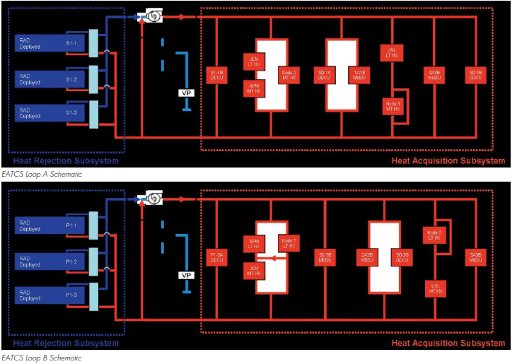
The External Active Thermal Control System is comprised of two independent loops that were designed so that a failure in one would not take down the entire external thermal control system. Both loops are physically segregated from one another to achieve redundancy and the fluid transport lines are buried within the truss structure to protect them from orbiting debris. If a loop fails to function, the EATCS continues to operate, but at a reduced capacity. Each loop collects heat from up to five Interface Heat Exchangers. The EATCS also provides ammonia resupply capability to the Photovoltaic Thermal Control Systems (PVTCS). All EATCS components are located outside the pressurized areas to prevent crew contact with ammonia.
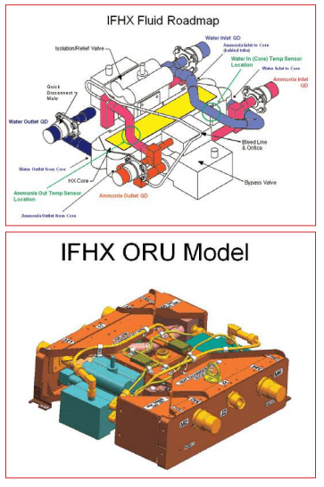
There are five interface heat exchangers (IFHXs) for each EATCS loop. The IFHX units transfer heat from the IATCS water coolant loops to the external ammonia coolant loops. Each IFHX core is a counterflow design with 45 alternating layers. IATCS water flows through 23 of the layers, while EATCS ammonia flows through the 22 alternate layers in the opposite direction. These alternating layers of relatively warm water and relatively cold ammonia help to maximize the heat transfer between the two fluids via conduction and convection. The heat exchanger core is a simple flow through device with no control capability.
The Photovoltaic Thermal Control System (PVTCS) consists of ammonia loops that collect excess heat from the Electrical Power System components in the Integrated Equipment Assembly (IEA) and transport this heat to the four PV radiators where it is rejected to space. The Photovoltaic Thermal Control System consists of ammonia coolant, 11 cold plates, two pump flow control subassemblies (PFCS), and one photovoltaic radiator (PVR). The Photovoltaic Thermal Control System can dissipate 6,000 watts of heat per orbit.
Each loop provides cooling to externally mounted cold plates. The cold plates contain electrical equipment that converts and distributes power to downstream ISS loads. Each ammonia loop contains four cold plates, two attached to Current‐to‐Direct Current Converter Units (DDCUs) and two attached to Main Bus Switching Units (MBSUs). Each cold plate Orbital Replacement Unit (ORU) is connected to the EATCS ammonia loop by self-sealing quick disconnect (QD) couplings and contains a finned cold plate, two or three strip heaters and a temperature sensor. The cold plates are installed such that the fins of the cold plate are positioned adjacent to corresponding fins on either the DDCU or the MBSU to facilitate heat transfer by radiation between the cooled equipment and the cold plate. Each DDCU cold plate measures 35 inches (88.9 cm) by 28 inches (71.12 cm) by 31 inches (78.74 cm) inches and weighs about 96 pounds (43.54 kilograms).
Circulation, loop pressurization, and temperature control of the ammonia is provided by the Pump Module (PM). Each ammonia loop contains a Pump Module Assembly (PM) ORU to provide flow and accumulator functions and maintain proper temperature control at the pump outlet. Each Pump Module consists of a single pump, a fixed charge accumulator, a Pump & Control Valve Package (PCVP) containing a firmware controller, startup heaters, isolation valves, and various sensors for monitoring performance. The accumulator within the Pump Module works in concert with the Ammonia Tank Assembly (ATA) tanks to compensate for expansion and contraction of ammonia caused by temperature changes and keeps the ammonia in the liquid phase through a fixed charge of pressurized nitrogen gas.
The Pump Module (PM) provides fluid pumping, fluid temperature control and system pressure control. The Pump & Control Valve Package (PCVP) provides flow control. A single pump in the PCVP circulates the ammonia. The Flow Control Valve (FCV) located within the PCVP regulates the temperature of the ammonia. The Flow Control Valve mixes “cool” ammonia exiting the radiators with “warm” ammonia that has bypassed the radiators. Loop A typically operates at 8,200 lb/hr and loop B at 8,900 lb/hr with the pumps turning at 14,000 and 14,700 revolutions per minute, respectively.
The accumulator located in the Pump Module provides auxiliary pressure control. The accumulator keeps the ammonia in the liquid phase by maintaining the pressure above the vapor pressure of ammonia and provides makeup ammonia in case of a leak. The accumulator works in conjunction with the Ammonia Tank Assembly to absorb fluctuations in the fluid volume due to varying heat loads through the expansion and contraction of its internal bellows. Nominal operating pressure for the loops is 300 psia at the pump inlet. The maximum system design pressure is 500 psia. Each Pump Module measures 69 inches (175.26 cm) by 50 inches (127 cm) by 36 inches (.91 cm) inches and weighs about 780 pounds (353.8 kilograms).
Flow Control Monitoring Failure Detection, Isolation and Recovery (FDIR) for high and low pressure conditions are monitored by Multiplexer/Demultiplexers (MDMs). For an over pressure, gaseous nitrogen pressure is relieved down to 360 psia when pump inlet pressure reaches 415 psia (active control). The Pump & Control Valve Package Inlet pressure, Radiator return pressure, and Bypass return pressure sensors are part of this system and two of three pressure readings are used to determine if an overpressure condition exists. The pump will shut down when the pump outlet pressure reaches 480 psia.
Low pressure (current limit set at 170 psia) is monitored by two methods to determine a low pressure condition (the higher of the two values to determine the limit). Low pressure conditions are monitored using the PVCP inlet pressure, radiator return pressure, and bypass return pressure sensors.
The Pump & Control Valve Package also maintains temperature set point control of the ammonia supplied to the Heat Acquisition Subsystem. The PCVP has a temperature control capability of 36°F (2.2°C) to 43°F (6.1°C) and it is set at 37°F ± 2 °F (2.8°C). The temperature control method is by a three-way mixing valve that mixes flow from the radiators and the Heat Rejection System (HRS) Bypass. Heaters on the HRS Bypass leg provide an additional level of control. Total heater power of 1.8 kW is split across two heater strips mounted on the HRS bypass lines (900 watts each). Pump outlet over temperature protection is provided by a Firmware Controller (FWC) in the PCVP that uses three PCVP outlet sensors to determine an over temperature condition and issues zero pump speed. Multiplexer/Demultiplexers (MDMs) use the Pump Module outlet sensor to determine an over temperature condition and pull power from the Solenoid Driver Output (SDO) card providing power to the Pump Module. The current limit is set at 65°F (18.33°C). The pump is also shut down when the PCVP firmware detects potential freezing in the IFHX.
Each ammonia loop contains an Ammonia Tank Assembly Orbital Replacement Unit (ATA ORU) to contain the heat transfer fluid (liquid ammonia) used by the EATCS loops. There is one Ammonia Tank Assembly per loop. The ATA ORU is used to supply makeup fluid to the system, to act as an accumulator in concert with the Pump Module accumulator and provide the capability to vent the ammonia loops by way of a connection to an external non‐propulsive vent. Each ATA primarily consists of two bellows ammonia tanks pressurized by an external nitrogen source, two internal survival heaters and two sets of quantity, differential pressure, absolute pressure and temperature sensors. The ATAs are isolatable and replaceable on orbit.
The ATA in combination with the Nitrogen Tank Assembly (NTA) provides fluid supply and primary system pressure control. The ATA acts as the primary accumulator for the EATCS in concert with the NTA. If required, it can also be used to replenish the PVTCS fluid lines. Each ammonia loop contains a Nitrogen Tank Assembly ORU to provide storage for the high pressure nitrogen used for controlled pressurization of the ATA.
The NTA is connected to the ATA by self‐sealing Quick Disconnects (QDs). Each NTA ORU primarily consists of a nitrogen tank, a gas pressure regulating valve (GPRV), isolation valves and survival heaters. The nitrogen tank provides a storage volume for the high‐pressure gaseous nitrogen, while the GPRV provides a pressure control function as well as nitrogen isolation and over pressure protection of downstream components. The NTA provides the necessary pressure to move the ammonia out of the ATA. The single high‐pressure tank contains nitrogen at 2,500 psia (@70°F, ground fill) and uses the GPRV to supply continuous pressure up to 390 psia in one psia increments. A back‐up mechanical valve limits the maximum nitrogen pressure to 416 psia. The GPRV provides pressure control as well as high‐pressure nitrogen isolation and overpressure protection of downstream components. The NTA has venting capabilities and over pressure controls. Each NTA measures 64 inches (162.56 cm) by 36 inches (91.44) by 30 inches (76.2 cm) inches and weighs about 460 pounds (208.65 kilograms).
Fluid Lines and external Quick Disconnects (QDs) provide the transportation path from the truss segments to the IFHXs. Connections between segments are made with flex hoses and QDs.
Heat collected by the EATCS ammonia loops is radiated to space by two sets of rotating radiator wings—each composed of three separate radiator ORUs. Each radiator ORU is composed of eight panels, squib units, squib unit firmware controller, Integrated Motor Controller Assemblies (IMCAs), instrumentation, and QDs.
Each Radiator ORU measures 76.4 feet (23.3 meters) by 11.2 feet (3.4 meters) and weighs 2,475 pounds (1,122.64 kilograms). Each ammonia loop contains one radiator wing comprised of three Radiator ORUs mounted on the Radiator Beam and six Radiator Beam Valve Modules (RBVM) and one Thermal Radiator Rotary Joint (TRRJ). Each Radiator ORU contains a deployment mechanism and eight radiator panels. The deployment mechanism allows the Radiator ORU to be launched in a stowed configuration and deployed on orbit. Each radiator ORU can be remotely deployed and retracted. Each individual radiator has two separate coolant flow paths which flow through all eight radiator panels. Each panel’s flow path has eleven flow tubes for a total of 22 Inconel flow tubes or passages (11 passages per flow path) per radiator panel; flow tubes are freeze tolerant. Flow tubes are connected along the edge of each panel by manifolds. Flex hoses connect the manifold tubes between panels. Each panel has a white (Z‐93) coating which provides optimum thermo‐optical properties to maximize heat rejection. The flow tube arrangement is designed to minimize ammonia freezing in the radiator. Each radiator path contains one Radiator Beam Valve Module (RBVM) as a part of the radiator wing. Six RBVMs are mounted on the radiator beams and truss segments. Two RBVMs service each radiator ORU. Each RBVM consists of an isolation relief valve, an isolation valve, an Integrated Motor Controller Assembly (IMCA), QDs, and pressure and temperature sensors. The RBVM controls the transfer of ammonia between the Radiator Assembly ORU and the rest of the EATCS loop. Each RBVM contains sensors to monitor absolute pressure, temperature and valve position within the ORU. Remote control venting of the radiator fluid loop is also available through the RBVM to facilitate radiator replacement and prevent freezing of the ATCS coolant during contingency operations. The RBVM provides flow path isolation in the event that a panel suffers micro‐meteoroid damage and also provides automatic pressure relief when the EATCS is over pressurized. Each RBVM weighs about 50 pounds (22.68 kilograms) and measures 24 inches (60.96 cm) by 20 inches (50.8 cm) x 5.4 inches (13.72 cm).
The rotation capability for each radiator assembly is provided through a Thermal Radiator Rotary Joint (TRRJ). The TRRJ provides power, data, and liquid ammonia transfer to the rotating radiator beam while providing structural support for the radiator panels. Rotation angles are determined via the Radiator Goal Angle Calculation (RGAC) algorithm which commands the Radiator Beam to put the radiators either “edge to the sun” during isolation phase of the orbit or “face to the Earth” during the eclipse phase.
The RGAC ensures the radiators stay cold enough so the heat can be rejected but warm enough so that the ammonia does not freeze. There is a temperature goal of –40 °F at the radiator outlet. The FHRC provides the transfer of liquid ammonia across the rotary joint and is capable of rotating 230 degrees, at ±115 degrees from its neutral position. (software command limit is ±105°); with a variable rotation speed of 0 to 45 degrees‐per‐minute. Each TRRJ measures approximately 5.6 feet (1.7 meters) by 4.6 feet (1.4 meters) by 4.3 feet (1.3 meters) and weighs 927 pounds (420.5 kilograms).
Software Thermal Control System (TCS) software is used to control and monitor the system. The TCS software executes actions such as system startup, loop reconfiguration, and valve positioning for flow and temperature control automatically or via commands from crew laptops or ground workstations. Telemetry from the various temperature, pressure, flow, and quantity sensors is monitored by TCS software and displayed on crew laptops or ground workstations.
In addition, Fault Detection, Isolation, and Recovery (FDIR) software is used to monitor the performance of the TCS and, if there is a problem, alert the crew and flight controllers. In some cases, FDIR software initiates recovery actions. In addition to the experts mentioned in the article, the author thanks Lupe Gonzales, The Boeing Company–IDS Space Exploration ISS Active Thermal Control Systems Manager, and Adam Morgan, Boeing Space Exploration Communications/ Public Relations, for information and help locating diagrams of the Space Station’s Active Thermal Control System.