Technical Paper #14
Sustainable Solutions for Agricultural Cold Storage: A Case Study
Author: Tania Herrera, Key Account and Product Engineer, Güntner U.S., LLC and Dan O’Brien, President, Zero Zone, Inc.
Abstract
This paper explores the potential of integrating CO2 refrigeration systems with energy savings alternatives to maximize sustainability and energy efficiency in agricultural cold storage facilities. With growing concerns over environmental impact and energy consumption, the adoption of ecofriendly refrigeration solutions is imperative. CO2 refrigeration systems offer significant benefits in terms of reduced global warming and ozone depletion potential compared with conventional synthetic refrigerants.
Introduction
The refrigeration industry has a significant environmental impact, both directly and indirectly, owing to its reliance on energy and chemicals that contribute to pollution and climate change. According to the International Institute of Refrigeration, the refrigeration industry represents around 17%–20% of the world’s total electricity consumption. This includes domestic, commercial, and industrial refrigeration units and is considered a significant portion of global energy usage.
Adopting more energy-efficient solutions in refrigeration systems has more benefits than just supporting a greener process; it helps companies comply with regulations, achieve financial savings, improve system reliability, and meet corporate sustainability goals. As environmental concerns and regulatory pressures continue to grow, reducing emissions from refrigeration systems is becoming a major concern.
Sustainable Refrigeration
Sustainable Systems
Sustainability refers to a way of living that allows people to coexist on Earth for a long time while meeting the needs of the present without compromising the ability of future generations to meet their own needs (United Nations, 1987).
Sustainable solutions in the refrigeration industry are vital for mitigating environmental impacts, enhancing energy efficiency, and ensuring long-term economic and ecological stability. A sustainable refrigeration system is designed to minimize environmental impact while maintaining efficiency.
The major factors that make a refrigeration system sustainable are summarized as follows:
- Eco-Friendly Refrigerants: Using low-global warming potential (GWP) refrigerants reduces greenhouse gas emissions. Options like natural refrigerants (ammonia, CO2, hydrocarbons) are often more sustainable than conventional synthetic products.
- Energy Efficiency: Implementing high-efficiency compressors, heat exchangers, and advanced control systems can significantly lower energy consumption.
- Renewable Energy Integration: Utilizing renewable energy sources (like solar or wind) to power refrigeration systems can greatly reduce their carbon footprint.
- Lifecycle Assessment: Considering the entire lifecycle of the system—from manufacturing to disposal—helps in selecting materials and designs that are less harmful to the environment.
- Heat Recovery: Capturing and reusing waste heat from the refrigeration process can improve overall energy efficiency and reduce resource consumption.
- Durability and Design: Designing systems for longevity and easy repair reduces waste and the need for replacement.
- Smart Technology: Incorporating the Internet of Things and smart controls can help optimize system performance and energy use based on real-time data.
Environmental Impact
Although the refrigeration industry is essential for food preservation, medical storage, and many industrial processes, it significantly contributes to climate change and environmental degradation through high energy consumption, the use of potent greenhouse gases, and resource depletion. The key contributors are:
- Electricity use
- Refrigerants
- Insulation and design
- Material management
The carbon footprint of a refrigeration warehouse can vary substantially, but it is generally driven by electricity use and refrigerant emissions. For a typical large facility, the carbon footprint can easily reach hundreds to thousands of metric tons of CO2e per year.
Companies can use the Greenhouse Gas Protocol to categorize their emissions into three scopes:
- Scope 1: Direct emissions to the atmosphere from sources that the company controls. An example is refrigeration leaks.
- Scope 2: Emissions that the company causes indirectly, stemming from where the energy it purchases and uses is produced. An example of this is electricity, heat, or steam. The impact of electricity use is highly dependent on the emission factor for the location, which in turn depends on how the power is generated, the proportion of renewable generation, and to some extent the time of use in a day, week, or year (ASHRAE, 2018).
- Scope 3: Indirect emissions from sources outside the organization’s control, created by a company’s value chain, such as purchased goods and services, waste disposal, and business travel.
Agricultural Cold Storage
The refrigeration system installed at this agricultural cold storage facility guarantees that the crops are stored at the appropriate temperature and humidity with the lowest possible energy usage. This is possible because the energy efficiencies of each component of the refrigeration system amplify each other. It was designed to reduce the carbon footprint and emissions of this facility while making it more energy efficient. The following system considerations make this refrigeration system more sustainable:
- Natural Refrigerant: The system is designed to work with CO2.
- Energy Efficiency:
- Multiple compressors with staged and modulating capacity control are implemented to adjust their power usage based on real-time demands (as we know, load varies throughout the year).
- The fan motors in the evaporators are controlled, adjusting their speed and operation by 40%. Once the room reaches the target temperature, the fans consume less energy at reduced speeds. Furthermore, the evaporators are defrosted using electric methods. Electric reheat banks were added to some evaporators to ensure proper control of relative humidity in the rooms.
- The electronic expansion valves at this facility regulate the flow of the refrigerant into the evaporator, ensuring precise temperature control.
- Adiabatic gas coolers with variable-speed fans use approximately 75% less water and produce little to no water waste compared with an evaporative condenser. The control system monitors the ambient conditions, in addition to the capacity demand, to maintain the minimum amount of water required to provide the necessary cooling. Adiabatic cooling also enables a lower leaving gas temperature, allowing the system to operate in subcritical mode for longer periods, which means the system operates well under lower temperature/ pressure conditions, ultimately saving energy.
- Sensors monitor moisture levels in the facility to maintain optimal room humidity and avoid weight loss in the product. •
- Insulation: The building was designed with insulation values that ensure minimal loss in temperature, approximately 1–2 °F of loss over a 24-hour period.
- Roofing insulation: Roofs are insulated using polyisocyanurate insulation with an R-value of 28. This is covered by a half-inch high-density cover board with an R-value of 2.5, using approved fasteners. The combined R-value of the roof is R-30.5.
- Wall insulation: Both the interior and exterior walls of the facility are insulated with R-19 and R-13 unfaced fiberglass batts, as well as R-19 unfaced fiberglass batts at hard-lid ceiling areas. The interior walls have three-inch panels, whereas the exterior walls have four-inch panels. Where the partition walls meet, the roof is insulated using polyurethane spray foam with an R-value of 19.5. Insulated metal panels: Insulated metal panels that make up the wall frame utilize insulation foam with R-8 per inch.
- Renewable Energy Integration: All the facility’s electricity is supplied by off-grid microgrid technology. The installation incorporates three levels of redundancy.
- The roof is equipped with a 1,200 kW rooftop solar array and 1,200 kW/2,400 kWh battery storage. With an expected load of 200–250 kW, the solar array and battery can power the facility for 12–18 hours per day. The microgrid infrastructure is also scalable, with provisions to incorporate additional solar panels if needed. If Madera’s grid capacity is expanded in the future, and if the need arises, power generation at this facility can also be connected to the electric grid.
- Two 1,200 kW low-emission natural gas generators are installed as backup power sources.
- A generator can be brought from offsite and plugged into the switchgear to ensure uninterrupted power in an emergency. •
- Smart Technology: The facility’s operations are enhanced by a cutting-edge software system. This software not only seamlessly manages diverse energy sources but is also inherently adaptive. It identifies and learns from usage patterns, discerning high- and low-demand periods throughout the day. Combined with weather forecast data, the system can anticipate potential energy demands and preemptively make necessary adjustments, leading to optimal operational efficiency.
Government Incentives
The U.S. government offers several incentives to encourage end users to adopt more sustainable options for refrigeration systems because they help reduce emissions, improve energy efficiency, protect the environment, and stimulate innovation. These measures are crucial for mitigating climate change, supporting public health and fostering sustainable economic growth. Some of the incentives are outlined as follows:
- Investment Tax Credit: This allows businesses to deduct a percentage of the cost associated with installing renewable energy systems, including certain energyefficient refrigeration technologies.
- Tax Deductions under Section 179D: This allows commercial building owners to deduct the cost of energy-efficient improvements, including refrigeration upgrades, directly from their taxable income.
- Carbon Credits and Cap-and-Trade Programs: Some states participate in regional initiatives that allow businesses to buy and sell carbon credits, creating a financial incentive to reduce emissions.
- Renewable Energy Tax Credits: Incentives for installing renewable energy systems (like solar or wind) indirectly help reduce CO2 emissions by promoting cleaner energy sources.
Calculation
Calculating the carbon footprint of a facility is important for environmental, financial, regulatory, and strategic reasons. The carbon footprint is used as an index for reducing environmental impact, improving efficiency, complying with regulations, and enhancing a company’s reputation and long-term sustainability. In this paper, the calculations of the carbon footprint for this installation are focused on the refrigeration system emissions, highlighting that Scope 1 factors are under the company can control and are most directly related to the refrigeration system.
To calculate the carbon footprint related to the Scope 1 emissions, the following information is needed:
- Energy consumption (electricity use)
- Carbon emission factor: Different regions have different carbon emission factors based on their electricity generation mix. This emission factor reveals how much CO2 is emitted per kWh of electricity consumed. The emission factor for California (where the installation is located) is 0.20553 kgCO2e per kWh
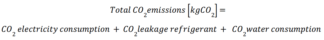
Formula to Calculate the Carbon Footprint Related to Energy Consumption:

• Estimate Emissions from Refrigerant Leakage
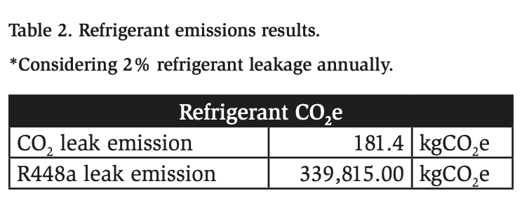
Refrigerant leakage is a major source of emissions in refrigeration systems, particularly when using refrigerants with a high GWP.

Herein, calculations were conducted for the installation with CO2 and an installation without a sustainable approach, using R448a (see Table 2).
Formula to Calculate the Footprint related to Water Consumption:

Total CO2 Footprint Calculation
The agricultural cold storage facility described in this paper consists of two 255,000-square-foot temperature-controlled warehouses located in Central California. Each warehouse can store up to 100 million pounds of product at maximum capacity. The design load is approximately 605 TR’s. The refrigeration system operates on single-stage compression (28 °F suction temperature), using a direct expansion CO2 system with adiabatic gas coolers.
For comparison, the alternate refrigeration system for the facility involves a direct expansion rack system using R448a and an evaporative condenser.
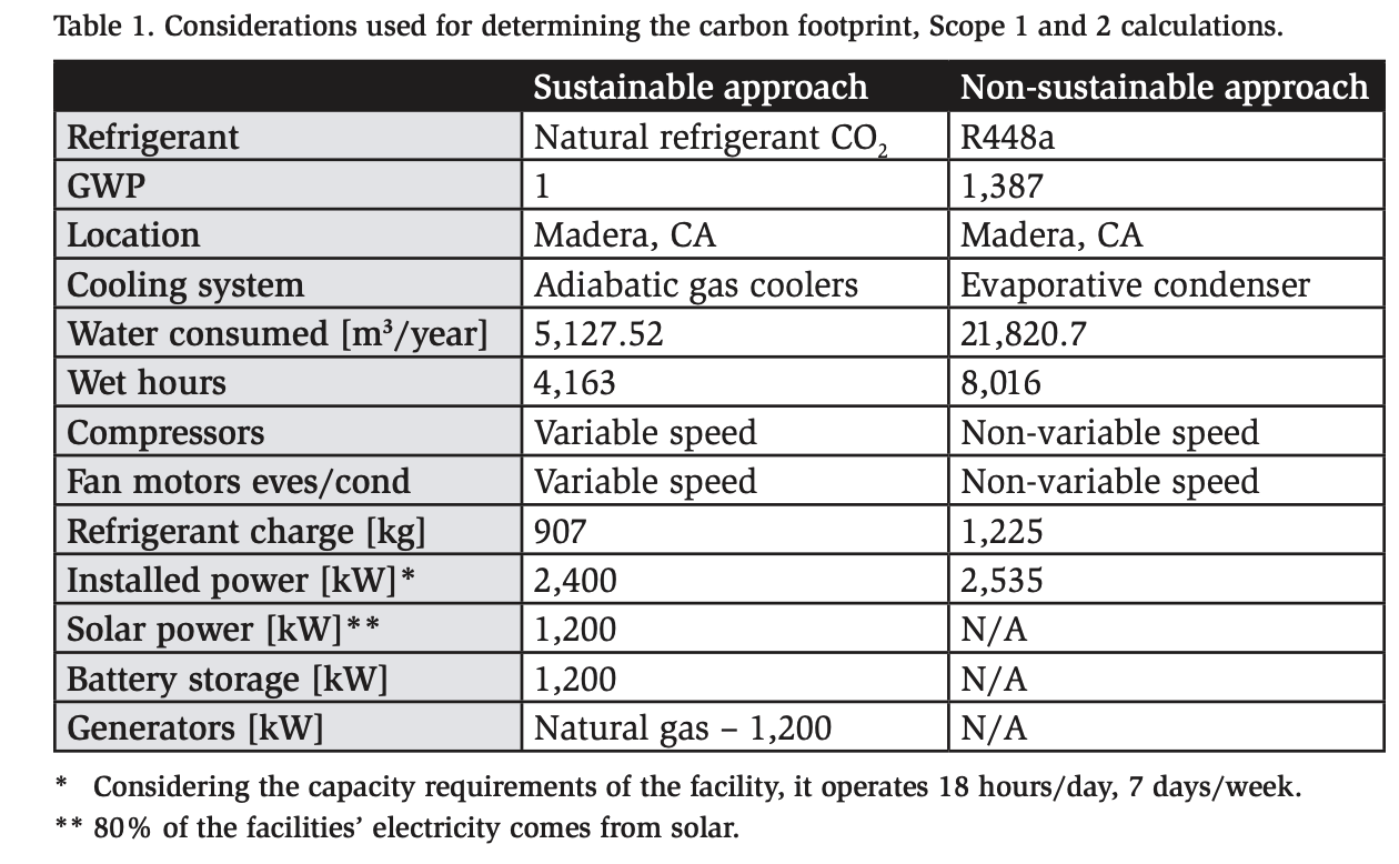
The calculation results for the Scope 1 (Refrigeration system) and Scope 2 (Electricity) emissions are shown in Table 1.
To calculate the total emissions of the refrigeration system, for Scope 1 emissions, the refrigerant leakage must be considered, as shown in the Calculations section. See Table 2 for the results.
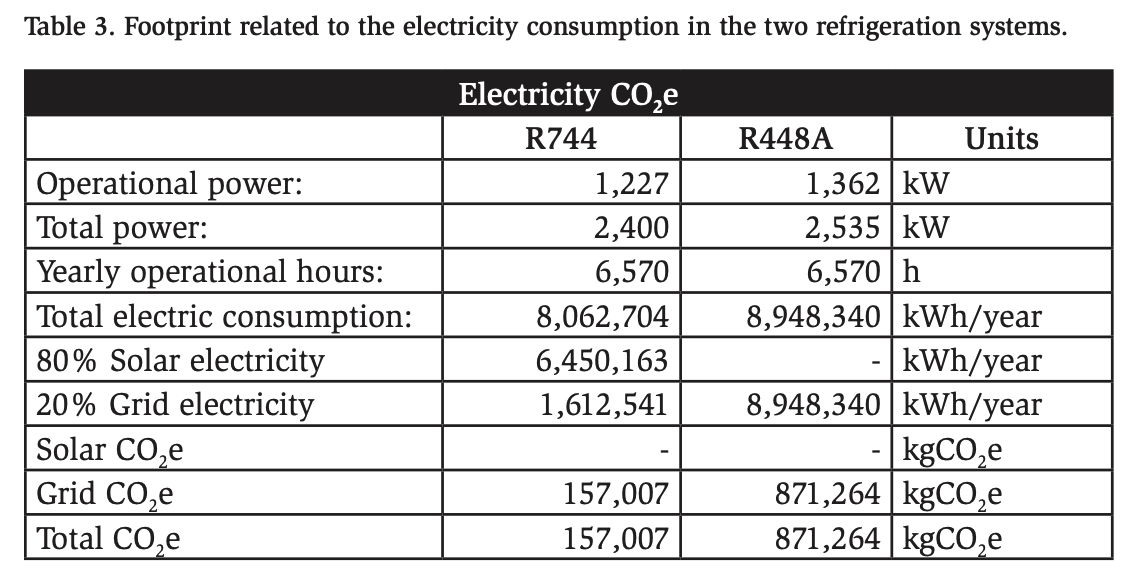
To calculate the emissions related to the facility’s energy usage, we assume that 80% of the total energy is generated by solar and 20% is supplied by the grid. For the alternate system, 100% of the energy is supplied by the grid.
Water itself does not directly emit CO2, but the energy and resources involved in its lifecycle contribute to the carbon footprint of a process. To calculate this, it is necessary to consider the emission factor for water, which is 0.001 kgCO2e (ASHRAE,2018). Table 4 shows the footprint related to the water consumption of the refrigeration system. The CO2 system uses an adiabatic gas cooler, and the alternate system uses an evaporative condenser.
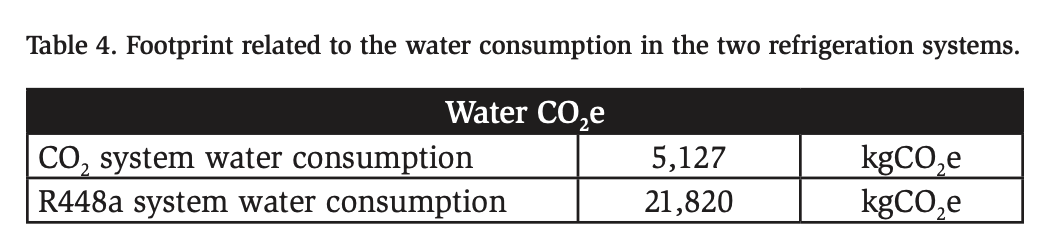
Table 5 shows the total CO2 emissions of the sustainable installation and the alternate solution.
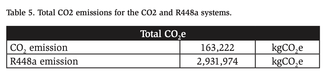
The sustainable system exhibits emissions reductions of up to 2,768,752 kgCO2e compared with the traditional system. This correlates to 4,038 round-trip flights from Chicago to Phoenix, or 156,585 servings of ¼ pound burgers, or 6,880,150 cups of coffee, or driving a 2020 Toyota Corolla on the Pacific Route (101) 5,820 times.
The drastic difference in emissions between the two scenarios demonstrates the benefits of using a low-GWP refrigerant, keeping refrigerant leakage low, supporting high energy efficiency (e.g., low fan power in evaporators and gas coolers, or using a rack design), and leveraging renewable energy sources (e.g., rooftop solar panels), resulting in a lower overall carbon footprint for the refrigeration system and lower Scope 1 and 2 emissions. Lowering Scope 1 and 2 emissions is a critical step for organizations to reduce their environmental impact, comply with regulations, save costs, and contribute meaningfully to the fight against climate change.
Conclusion
Using a natural refrigerant solution in combination with renewable energy sources can provide a significant reduction in greenhouse gas emissions during the operation of the refrigeration system.
By upgrading to more energy-efficient adiabatic technologies, companies can lower their power consumption, which not only reduces Scope 2 emissions (emissions from purchased electricity) but also lowers operational costs.
Choosing a natural refrigerant, such as CO2, can significantly lower the system’s Scope 1 emissions (direct emissions from the facility) and prevent high-GWP gases from reaching the atmosphere.
Although sustainable refrigeration facilities require a commitment to sustainability from all participants involved in all stages of the supply and production life cycle, the most critical participant is the original owner/developer of the facility because the potential for the facility to be sustainable is most strongly determined during the engineering and design phase of the project.
Governments around the world are continuously introducing new regulations and phasing out hydrofluorocarbons through mechanisms like the Kigali Amendment to the Montreal Protocol and the European Union’s F-Gas Regulation. These regulations impose strict limits on the use of high-GWP refrigerants and encourage the adoption of low-GWP alternatives.
Reducing carbon emissions ensures regulatory compliance, helps businesses avoid fines, and ensures they are prepared for future legislative changes.
Finally, this facility maximizes sustainability and efficiency within the agriculture industry by:
- Minimizing the crop loss post-harvest: A climate-controlled facility located near the harvest site keeps crop losses at the lowest level.
- Increasing flexibility in the supply chain: Farmers can deliver commodities to markets on a just-in-time basis.
- Utilizing clean technology: By implementing innovative refrigeration, building envelope, microgrid, and inventory management systems, Amond World leads the industry in energy and operational efficiency.
References
2020 factors (Published: Jan 2022) / https://www.epa.gov/egrid/historical-egrid-data
Amond World. (2023). A Cutting-Edge Facility Solves California’s Agricultural Supply Chain Bottleneck. https://acrobat.adobe.com/id/urn:aaid:sc:VA6C2:6c3d4ad8-d6ee4324-b7d5-f50c3265505a
ASHRAE. 2018a. ASHRAE Greenguide: Design, Construction, and Operation of Sustainable Buildings, 5th Edition. Atlanta: ASHRAE.
ASHRAE. 2018b. ASHRAE Handbook—Refrigeration. Atlanta: ASHRAE CO2everything. (s. f.). https://www.co2everything.com/category/cars
CO2everything. (s. f.). https://www.co2everything.com/category/food
EPA. 2006. Life cycle assessment: Principles and practice. Cincinnati, OH: Environmental Protection Agency, National Risk Management Research Laboratory. www.epa.gov/nrmrl/std/lca/pdfs.
Financing and Incentives. (s. f.). Energy.gov. https://www.energy.gov/energysaver/ financing-and-incentives
Garnett, T. 2011. Where are the best opportunities for reducing greenhouse gas emissions in the food system (including the food chain)? Food Policy 36:S23–S32.
Story of Stuff video. Understanding how businesses work: https://www.youtube. com/watch?v=9GorqroigqM
United Nations. (s. f.). Sustainability | United Nations. https://www.un.org/en/ academic-impact/sustainability#:~:text=In%201987%2C%20the%20United%20 Nations,development%20needs%2C%20but%20with%20the
Acknowledgments
Thanks to Barnett Refrigeration and the Güntner Sustainability Department.