


2025 Technical Paper #8
Applications of Ammonia and Carbon Dioxide for Decarbonization and Markets Other Than the Food and Beverage Refrigeration Industry
Author: Paul Danilewicz, P.E., Santosh Yarlagadda Enerflex Energy Systems, Inc. Houston, Texas
Introduction
Ammonia (NH3) and carbon dioxide (CO2) refrigerants are commonly used in food and beverage markets and other industrial refrigeration systems. They have also been used in the plants producing chemicals, industrial gases, and fertilizer. With recent emphasis on global warming and decarbonization, there are emerging new opportunities for ammonia and carbon dioxide use outside conventional closed loop industrial refrigeration systems.
The interest in hydrogen as a clean fuel has recently rapidly grown. But widescale long distance transportation of hydrogen is not practical because liquefaction and regasification of hydrogen is difficult and expensive. Additionally, transporting large quantities of liquid hydrogen at elevated pressure is cost prohibitive. Ammonia, for those reasons, became a carrier of choice for transportation and storage of hydrogen. However, the storage and import or export facilities require large refrigeration and boil-off gas systems equivalent to those associated with storage and transportation of Liquefied Petroleum Gases (LPG) such as propane, propylene, or butanes.
Similar systems are considered for transportation and storage of large quantities of carbon dioxide that could be used as a feedstock in the chemical plants, for Enhanced Oil Recovery (EOR) projects, beverage carbonization, or to be injected for permanent sequestration.
The latest restrictions on use of synthetic refrigerants are also forcing industries to find alternatives to otherwise commonly used freon refrigerants. Ammonia or carbon dioxide refrigerants are good options having zero or near zero Global Warming Potential (GWP) compared to, for example R-134A refrigerant, which has GWP above 1,400. For those reasons ammonia/carbon dioxide cascading systems are becoming more popular for low temperature applications in large-scale industrial applications.
Also, large heat pump applications can utilize ammonia or carbon dioxide as a refrigerant. The high latent heat of ammonia is ideal for district heating applications that will need large quantities of heat, large machinery and power. Carbon dioxide for the equivalent compression ratios will have high discharge temperatures which will also benefit heating requirements.
Ammonia Production – Historical and Current Context
Ammonia production is a large industry. Most of the production plants utilize an ammonia synthesis process developed in early 1900 in Germany by Franz Haber. After proving the process, Haber patented the design and subsequently sold it to BASF, which in turn further tested and improved it under the direction of Carl Bosch. The ammonia production process is today called the Haber-Bosch process.
The first large scale ammonia plant was built by BASF in Germany in 1913 and had a capacity of 20 metric tonnes per day to 30 metric tonnes per day (44,100 pounds to 66,150 pounds of ammonia per day). Modern ammonia plants can produce hundreds of times more ammonia. The largest production complex in the world is a CF Industries plant located in Donaldsonville, Louisiana, which can produce about 4 million tonnes of ammonia per year (24 million pounds per day). The total worldwide production of ammonia, as of 2023, stood at approximately 240 million metric tonnes per year. The majority of ammonia is used as a feedstock in the production of the fertilizers.
Ammonia Plant Design
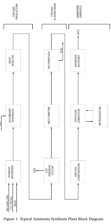
Typical Haber-Bosh process consists of a steam methane reformer, gas purification train, and ammonia synthesis module.
Steam methane reformer combines natural gas (majority methane) and air and produces syngas, which is a combination of hydrogen, nitrogen, carbon monoxide, carbon dioxide, and some residue methane. Considering ammonia is a combination of nitrogen and hydrogen, other components within the gas stream must be removed. The removal starts in a shift reactor, which converts carbon monoxide into carbon dioxide and then followed by an absorption system, which is typically an aminebased plant. In the amine plant, carbon dioxide is absorbed from the gas stream and then released into the atmosphere. From the amine plant the gas flows into a methanation reactor, in which residue carbon oxides are converted into methane and water. Finally, the process gas flows into the ammonia synthesis unit in which most of the components are converted into ammonia gas. The synthesis is only 20% efficient, thus the plants require large recycle loop to fully utilize the syngas. Eventually, the ammonia gas is cooled, condensed, and produced as an anhydrous ammonia at around -4°F (-20°C).
A block schematic of a typical ammonia plant is shown in Figure 1.
Some plants utilize coal as the source of syngas. In those designs coal is gasified by heating at very high temperatures resulting in gas having similar components to those achieved by a typical steam methane reforming process. The plants require Air Separation Units (ASUs) for production of oxygen required during the gasification process. China, the largest producer of ammonia in the world, utilizes coal in most of its ammonia plants. China has access to a lot of coal, however not as much natural gas.
Ammonia plants require substantial amounts of energy. Typical synthesis reactors operate between 1,000 psi and 3,000 psi (60 bar to 200 bar) and temperatures of 600°F to 1000°F (300°C to 500°C). Steam methane reformers require large quantities of high temperature, and medium pressure steam.
Hydrogen, a Critical Part of Ammonia Production
Having a source of hydrogen is a critical part of ammonia production. Nitrogen is plentiful, considering air is about 80% nitrogen. Hydrogen, on the other hand, must be produced. During production of hydrogen from natural gas or coal, large quantities of carbon dioxide are released into the environment. The estimates show that for every ton of ammonia produced, anywhere between 1.5 tons to 3 tons of carbon dioxide are released. Based on current production levels of ammonia, the carbon dioxide emissions generated during ammonia manufacturing are anywhere between 360 million and 720 million metric tonnes per annum.
The world needs ammonia but also tries to minimize the emissions of carbon dioxide because carbon dioxide contributes to global warming. Ammonia producers, incentivized by the governments are looking for ways to minimize these emissions.
Renewable and Non-Renewable Ammonia
Based on the source of hydrogen used in production, ammonia can be classified as grey, blue, or green.
Grey or non-renewable ammonia is the most produced and utilizes hydrogen derived from natural gas, coal, or other petroleum products. As discussed above, majority of the hydrogen plants utilize Steam Methane Reforming (SMR) process with natural gas and steam as feed sources. Other similar technologies utilize autothermal reforming or partial oxidation processes. During autothermal reforming, hydrocarbon feed is simultaneously reacted with steam and air to produce hydrogen. During partial oxidation hydrocarbons are reacted with oxygen to produce hydrogen. Other less common technologies include methanol steam reforming or thermocatalytic cracking of methane. All these processes, except for thermocatalytic cracking of methane, generate carbon dioxide as a byproduct.
The blue ammonia concept utilizes grey ammonia production technologies with capturing and sequestering rather than releasing carbon dioxide to the environment.
There has been a significant push over the last four years towards development of sequestration technologies for carbon dioxide. About 20 years ago, University of Illinois and ADM ran pilot projects in Illinois in which sequestration wells were drilled and carbon dioxide injected into the ground. These projects were successful, and similar concepts have been tried elsewhere with mixed successes. The wells must be drilled to inject gas or liquid into the ground. True carbon dioxide sequestration wells are categorized by the Environmental Protection Agency (EPA) as Class VI Wells. They are expensive to drill and develop and require EPA permits which have taken a long time to obtain. There have been only a few of these wells approved as of the end of 2024. The alternative is to utilize Class II Wells, which are typically used for Enhanced Oil Recovery (EOR) process. These wells, commonly used in oil production, are well known, easier to permit and less expensive to develop. However, the tax incentive granted by governments are much less if carbon dioxide captured during the production of hydrogen is used for other purposes rather than sequestered in a “tomb” inside the earth. Alternatively, carbon dioxide can be captured and liquefied as a food grade or non-food grade liquid product. This technology is well known and for the most part, utilizes ammonia refrigeration systems to convert gaseous carbon dioxide into a liquid product.
Green or renewable ammonia is produced using hydrogen that is obtained without any carbon dioxide generation. The most common technology to accomplish this is through the electrolysis of water. During this process, electric DC current between a cathode and anode is applied to water. The electric energy splits the water into hydrogen and oxygen, both gases are released and can be captured. On a volume basis, electrolysis generates twice as much of hydrogen versus oxygen. Obviously, the electrolyzers used through electrolysis require water and power. For a fully green ammonia the electricity cannot be generated by burning fossil fuels. However, fossil fuels such as coal and natural gas are the most common sources of energy for power generation. This leaves solar, wind, and nuclear power as sources of electricity for production of green hydrogen. The non-fossil fuel power generation process in addition to the requirement of fresh-water availability create their own challenges due to the scalability costs, reliability and public acceptance.
The power required to produce ammonia from fossil fuels ranges between 8 MWh/ ton and 12 MWh/ton of ammonia produced. The renewable ammonia requires 10 MWh/ton to 12 MWh/ton. Typical electrolyzers available in the market can generate 10 MW to 20 MW of power thus generate enough hydrogen for under 50 tons of ammonia production per day. For truly industrial scale facility custom built or dozens of industrial size electrolyzers would be required in addition to large renewable electricity power plant.
NEOM green hydrogen plant under development in Saudi Arabia will produce 200,000 tons of green hydrogen per year or 1.2 million tonnes per year of renewable ammonia. The estimated cost of the facility is about $7 billion. According to the company, the production will utilize 4 GW of renewable power obtained from wind and solar energy. Ammonia produced by the facility will be exported to the United States and Europe and most likely other areas.
Ammonia Users Outside of Refrigeration
Ammonia is the main refrigerant in food and beverage market. The oil and gas industry has traditionally used hydrocarbon refrigerants such as propane, propylene, ethane, and propylene. Commercial and residential facilities mainly standardized on various types of synthetic freons. The size of the food and beverage market is large with many meat, fish, and vegetable processing plants and cold storages throughout most of the countries. Ammonia is also the refrigerant of choice in the recreational industry. Ammonia absorption systems have also been installed in the facilities in which waste, low grade heat is available.
There are however many other uses of ammonia outside of refrigeration. One of the most common uses is utilization of ammonia as a feedstock for fertilizer production. The main product used as the fertilizer is called urea. Urea, the fertilizer having the highest nitrogen content of all solid nitrogenous fertilizers commonly available, is produced by synthesis of liquid ammonia and gaseous carbon dioxide utilizing BoschMeiser urea process, named after Carl Bosch and Wilhelm Meiser who patented it in 1922. The production of urea is a two-step process combining liquid ammonia and gaseous carbon dioxide, which are reacted at pressures above 2000 psi (138 bar) and temperatures around 400°F (204°C). The process requires significant amount of compression power to generate high pressure carbon dioxide. Liquid ammonia is pumped which requires less energy than compressing gas. The final product is in a solid form, produced as prills, granules, pellets, or crystals.
Considering that conventional ammonia production plants generate large amounts of carbon dioxide; the urea plants are almost always located next to the ammonia plants. Typical emissions of carbon dioxide during the production of ammonia exceed the requirements for carbon dioxide of the adjacent ammonia plant, making a combined facility a logical choice.
Ammonia and urea have also been used to control emissions of Nitrogen Oxides (NOx) generated in the exhaust of internal combustion engines, gas turbines, and other hydrocarbon burning devices. Nitrogen oxides are pollutants that contribute to the formation of smog and acid rain. Typical emission control systems are called Selective Catalytic Reduction (SCR). The SCR system utilizes a water-based urea solution, which is injected into the exhaust stack of the engine. During this process, urea undergoes hydrolysis, which produces ammonia. Ammonia reacts with NOx in the catalytic elements. The reaction produces nitrogen gas and water vapor and reduces the NOx levels in the exhaust gas. Large scale, industrial SCR systems utilize direct ammonia injection into the exhaust stack. Smaller facilities having personnel not familiar with proper ammonia handling procedures use urea instead.
Ammonia is also utilized as a feedstock in the production of ammonium nitrate, which is used as a fertilizer and as an explosive. Ammonium nitrate is produced by a reaction of anhydrous ammonia gas and concentrated water solution of the nitric acid, which produces concentrated water solution of the product, which is then solidified to form prills or granules after excess water is evaporated. Ammonium nitrate fertilizer is used by many vegetable growers, in pasture fertilization, etc. As an explosive, ammonium nitrate is used in a variety of explosive blends for mining and other industries.
Ammonia is considered as a replacement fuel for combustion processes. In particular, it is investigated as a source of fuel for internal gas engines and gas turbines. Ammonia is carbon free, includes three atoms of hydrogen and it can be stored and delivered as a liquid. The challenges associated with using ammonia as fuel are due to ammonia’s high ignition temperature and low flame velocity, which is only onefifth of methane and slow kinetics of the chemical reaction. Initially, blending of ammonia with typical hydrocarbon fuels has been investigated to overcome some of these limitations. Currently there are dual-fuel internal combustion engines and gas turbines coming onto the market designed to operate on just ammonia. The designs include high pressure, preheated mixing of ammonia fuel and air, modified engine cylinder or gas turbine blades designs and SCR emission control systems to minimize NOx emissions.
Finally, ammonia can be used as a hydrogen carrier. Transportation of pure hydrogen is challenging. At atmospheric pressure, hydrogen boils at below -420°F. Thus, liquefaction of hydrogen is difficult and expensive. In the gaseous form, hydrogen is very light considering its molecular weight is 2 pound/pound-mole. Ammonia’s molecular weight is 17 pound/pound-mole, which means that ammonia is 8.5 times heavier. For those reasons, liquefied ammonia is more suitable for road, rail, or ocean transport and it can be used to move hydrogen generated in one part of the world to a location many thousands of miles away.
Environmental Policy Implications on Ammonia and Carbon Dioxide Industries
The recent emphasis on addressing global warming and decarbonization creates new opportunities for ammonia and carbon dioxide use inside and outside of conventional closed loop industrial refrigeration systems.
The interest in ammonia and hydrogen as clean fuels has recently been rapidly growing. But widescale long distance transportation of hydrogen is not practical because liquefaction and reliquefication of hydrogen is difficult and expensive. Additionally, transporting large quantities of liquid hydrogen at elevated pressure is cost prohibitive. Ammonia, for those reasons, will most likely become a carrier of choice for transportation and storage of hydrogen. The facilities will require large refrigeration systems similar to those associated with storage and transportation of LPG such as propane, propylene, or butanes.
Comparable systems are considered for transportation and storage of large quantities of carbon dioxide that could be used as a feedstock in the chemical plants, for EOR projects, beverage carbonization or for injection, and for permanent sequestration in suitable earth formations, which may be located at locations that could not be connected to source via pipelines.
Transportation of Ammonia and Carbon Dioxide
Ammonia produced in the synthesis plant can be distributed to other users in cylinders, trucks, or via rail. Typical ammonia cylinder will hold 150 pounds (68 kg) of liquid or 30 gallons (114 liters). Standard liquid trucks can carry about 6,000 gallons (23,000 liters) of liquid. Railcars’ capacities vary between 20,000 gallons and 30,000 gallons (76,000 liters to 113,000 liters). Transportation of ammonia from overseas will require the use of the ocean carriers. There are three (3) basic types of ocean-going vessels available for transportation of volatile liquid products; pressurized, semi-pressurized, and refrigerated. The refrigerated carriers have the largest capacity. The capacity of the refrigerated ship is roughly 8 to 10 times larger than the capacity of the pressurized or semi-pressurized vessels.
The tanks used for carrying volatile liquids on board of the ships can be membrane type or independent self-supporting. The membrane vessels are usually very large and utilized mainly for carrying LNG. The independent self-supported tanks are classified as type A, B, and C by International Code for Construction and Equipment of Ships Carrying Liquefied Gases in Bulk or IGC. Type A tanks are a box or prismatic shaped to fit the ship’s hull. Type A tanks are usually utilized for transporting large loads on board of fully refrigerated ships. Type B tanks are typically spherical and utilized for shipping intermediate loads on board fully refrigerated or semipressurized ships. Type C tanks are horizontally placed cylindrical or spherical and used for smaller loads on board pressurized or semi-pressurized ships.
The fully refrigerated ships typically utilize Type A tanks. The design of the storage tank is determined by Maximum Allowable Relief Valve (MARV) setting. Typical MARV for fully refrigerated tanks is less than 10 psig (0.7 barg) with common design pressures of about 4 psig (0.28 barg). These tanks are suitable for storing liquids at temperatures -54°F (-48°C) or higher with some references listing minimum liquid temperature as low as -58°F (-50°C). The capacities of these ships can be up to 27 million gallons (100 million liters). The ships having capacities larger than 19 million gallons (72 million liters) are designated as Very Large Gas Carriers (VLGCs).
The semi-pressurized ships are typically smaller than fully refrigerated vessels, designed for MARV setpoints up to 70 psig and 100 psig (5 barg to 7 barg) and typically operating at pressures of 50 psig (3.5 barg) or less. Like the fully refrigerated vessels, the cargo hold of these ships is designed for minimum liquid temperature of -54°F (-48°C). The capacities of semi-pressurized ships typically do not exceed 8 million gallons (30 million liters).
The pressurized ships are the smallest within the fleet. They are designed to operate at MARV setpoints up to approximately 260 psig (18 barg) and typically designed for liquid temperatures of 32°F (0°C) or higher. The pressurized tankers have typical liquid carrying capacities of less than 1 million gallons. The size limitation of these ships comes mainly from their weight due to the wall thickness required for tanks to be capable of storing fully pressurized cargo.
Ammonia liquid can be transported via all three types of ships. At atmospheric conditions, however, carbon dioxide does not exist as liquid. The triple point for the substance is at the pressure and temperature of 75.5 psia (5.2 bar) and -69.9°F (-56.6°C). For that reason, transportation of carbon dioxide on fully pressurized ships is not possible. Semi-pressurized or fully pressurized ships must be used limiting the quantities of carbon dioxide per ship load.
Typical Components of the Liquefied Gas Export Facility
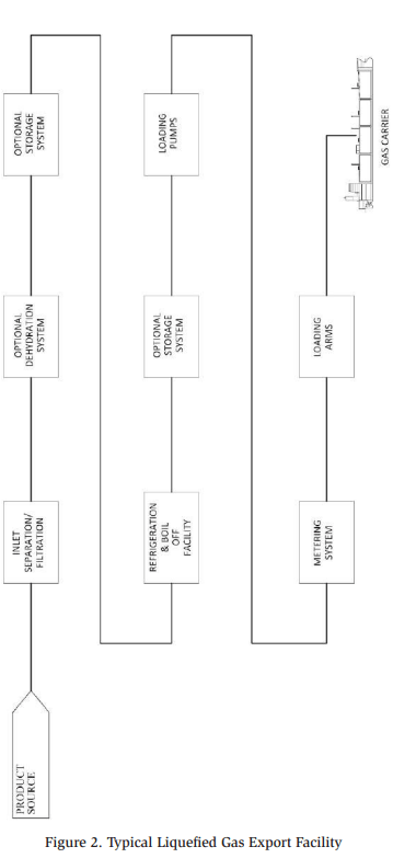
Upon arrival via a pipeline at the export facility, liquid is directed to storage vessels or sent directly to the processing equipment. If pipeline product contamination is a concern, inlet filters and separators will be installed upstream of the storage tank. Dehydration system may also be needed to prevent water freeze-up and/or tank corrosion. Most of the cargos will be shipped on board of semi or full refrigerated vessels and the product transport temperatures will be well below the triple point of water. Therefore, free water in the product stream is not desirable. Typically, a solid bed type desiccant dryer will be required to reduce the water content of the feed. The solid bed dehydration facility will require a dry product vaporizer and superheater for the regeneration gas, considering that other sources of the regeneration gas are typically not available on site.
Once feed is treated and dried at high pressure and temperature, it flows through the refrigeration facility and onto the ship or it can be stored at elevated pressure and temperature. It can also be refrigerated and stored in low pressure storage tanks. Once refrigerated, the feed will be pumped using centrifugal pumps onto the carrier. Before being delivered onto the ship, the product will flow through a metering station and loading arms located at the pier.
A block schematic of a typical liquid product export facility is shown in Figure 2.
The facility design feed rates and product load out rates are typically different considering that the ship loading process is inherently a batch type. Typically feed rates are lower and load out rates higher due to the desire to limit the ship’s loading time and to minimize the power requirements of the main refrigeration system. Smaller refrigeration systems can run continuously rather than intermittently or being forced to operate in recycle hot gas by-pass mode.
Refrigeration and Boil-off Facilities for Liquid Product Export
The purpose of the refrigeration system in a liquid export facility is to receive a warm, medium, or high-pressure liquid feed and convert it to a low pressure and low temperature product suitable for loading onto the ship. The product specifications will depend on the gas carrier that will be used to ship the product. In general terms, liquid supplied on board will be less than approximately 50 psig (3.5 barg) and maintained at a saturation temperature.
The refrigeration facilities can be divided into two general types: direct and indirect systems. The direct or open systems use the product itself as the refrigerant chilling it through a series of flashes down to the desired product pressure and temperature. In indirect or closed systems, the product is chilled via a conventional closed loop refrigeration system utilizing a series of heat exchangers before the product pressure is reduced.
In addition to the product refrigeration, boil-off gas handling and condensing needs to be considered for the export facility. Most of the boil-off gas will be generated during product loading to the storage tanks or ship holds due to vapor displacement. Unless the storage tank pressure is allowed to vary during loading and unloading process, as liquid is supplied to the tank, the vapor inside will be pushed out and must be removed, recompressed and in most cases re-condensed before returning it as liquid back to the tank. The flow rate of displaced vapor will be directly proportional to the product loading rate because on a volumetric basis, for a given amount of liquid entering the tank, the same amount of gas must leave the tank. The opposite will be true during the tank unloading process during which vapor needs to be supplied to the tank as the product is removed to maintain constant tank pressure. Liquid vaporizers are quite often employed for that purpose.
Boil-off gas will also be generated in storage vessels filled with liquid product due to an ambient heat leak and changes in atmospheric pressure. In general, the boil-off gas compression and condensing systems are much smaller than the refrigeration compression needed to chill the product itself.
This also applies to the vapor handling inside the ship storage tanks. Once product flows onto the ship, the vapors from the ship’s storage tanks will be displaced and will require recompression. These vapors are typically handled by compression and condensing equipment located on board of the ship.
Open or Direct Refrigeration Systems
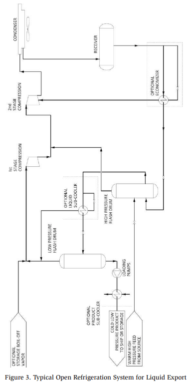
In a typical direct system, the high pressure and temperature feed arrives at the facility, and it is flashed to an intermediate pressure and temperature in the highpressure flash tank. Feed cooling is achieved via auto refrigeration effect, in which a portion of the product is vaporized due to the removal of heat from the balance of the stream. The flash vapor generated in the process is compressed by the second stage of the compression system while liquid leaves the flash tank. The intermediate pressure and temperature liquid can be optionally sub-cooled before flashing it again in the low-pressure flash vessel. The low-pressure flash vapors are then compressed by the first stage of the compression system. The low pressure and temperature product is then pumped into the refrigerated storage tanks or directly onto the ship. The flash vapors removed by both stages of compression are then condensed and returned to the system through a high-pressure flash vessel.
A schematic of a common arrangement of an open system is shown in Figure 3.
Handling of boil-off gas in open systems is straight forward. The boil-off gas can be combined with the low-pressure flash vapors generated during main product chilling, recompressed, condensed, and returned into the product stream via intermediate flash vessel.
A direct refrigeration system is preferred for chilling ammonia and carbon dioxide considering both are single component liquids.
Closed or Indirect Refrigeration Systems
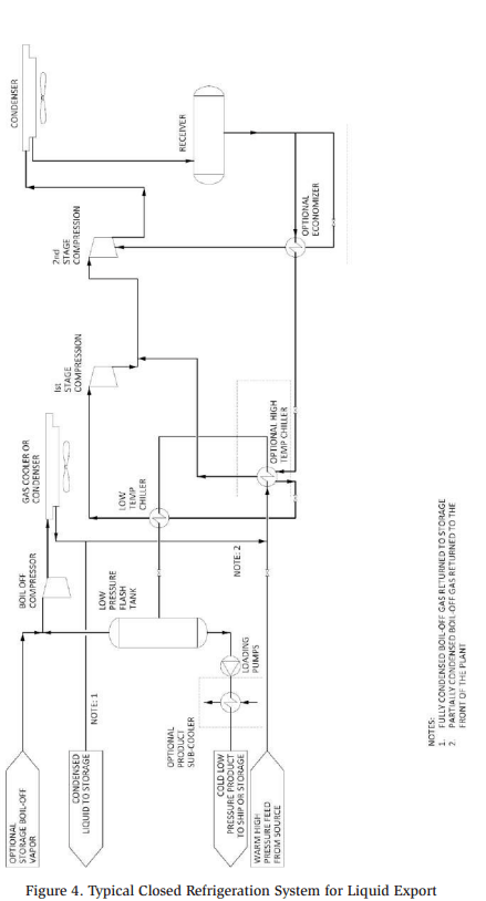
In indirect systems, warm high-pressure feed is chilled in a series of refrigerated heat exchangers before its pressure is reduced at the low-pressure flash tank. From the tank, the low pressure and cold temperature liquid product is pumped to storage or onto the ship. Indirect systems utilize a closed-loop multistage refrigeration system and require a separate compression facility for handling the flash gas generated at the low-pressure separator or storage tank.
A typical export facility will consist of single, or two feed chillers arranged in series. The second stage compressor provides refrigeration for the high temperature chiller and the first stage compressor services the low temperature chiller. The refrigeration system operates as an independent loop from the feed stream and can utilize any refrigerant suitable for the operating conditions. The role of the refrigeration system is to subcool high-pressure feed before flashing it down in the low-pressure flash tank from which cold liquid can be pumped onto the ship or into the storage tank.
A schematic of a common arrangement of a closed system is shown in Figure 4.
The closed systems are preferred for chilling feed having light ends or varying composition. The refrigeration loop operates independently from the incoming stream and can handle any liquid if the feed inlet pressure, temperature, and flow rate are within the plant design parameters. The design provides for plant operating flexibility. Indirect systems are less efficient than direct because the chilling requires heat transfer surfaces, which in turn require approach temperatures between the refrigerant evaporating temperature and liquid temperature leaving heat exchanger.
The indirect system design requires separate compression equipment for boil-off and feed flash gas because the refrigeration loop operates independently from the main product stream. The boil-off gas will typically be compressed and cooled in an air cooler. Depending upon the anticipated boil-off gas composition and the proposed facility arrangement, the boil-off gas can be fully condensed and returned to the storage/low pressure vessel or partially condensed and recycled back to the plant inlet.
Final Product Sub-Cooling
The liquid product in the low-pressure flash vessel is at its bubble point or saturation temperature. Sometimes additional liquid product sub-cooling may be desired after the product loading pump to eliminate liquid flashing between the refrigeration or storage system and the ship. The additional cooling is typically provided utilizing a separate refrigeration chiller.
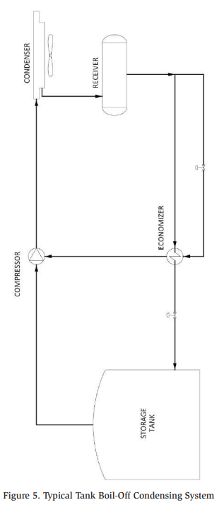
Handling of Storage Tank Boil-off Gas
The boil-off gas recompression can be incorporated into the refrigeration system or handled by independent equipment. If an independent system is required, it typically consists of multiple compressors removing the vapors generated in the tank and compressing them to the condensing pressure. The condensed liquid is then returned to the storage tank. The compression process can be achieved using a single- or two-stage (economized) cycle to reduce the overall power requirements and the equipment size.
There are multiple factors contributing to vapor generation in the storage tank, including atmospheric heat ingress to the tank, heat imparted from recirculation pump, flash gas generated during product fill, vapor displacement during product fill (piston effect), and atmospheric pressure changes. Considering high variability of the vapor generation depending on whether the tank is being filled or placed in a holding mode, the compression equipment load will vary significantly depending on the tank operating mode
Typical boil-off gas handling facility schematic is depicted in Figure 5.
Export versus Import Terminal
Once the product is refrigerated, liquefied, and loaded onto the ship, it will travel to an import terminal. Arriving product will be maintained as refrigerated liquid by the ship’s boil-off and re-liquefaction system. An import terminal will consist of a metering system, unloading pumps, storage tanks, and the boil-off system capable of handling vapor displacement during the unloading of the product from the ship and loading it into the storage vessel. The boil-off system design principle will be the same as those employed at the export facility. The compression equipment will have to be able to handle the largest load, typically associated with the liquid loading and unloading of the tank, as well much smaller vapor displacement due to the heat leak or minor changes in the barometric pressure. Typically, compression equipment will be provided with some redundancy to assure that the tank vapors can be re-liquefied even if one of the compressors fails during operation.
Components of the Refrigeration Systems
Typical components of the refrigeration system will include oil flooded screw compressors, refrigerant condensers, pressure vessels, and heat exchangers with an integrated control system. The refrigeration and boil-off compression is designed in multi-stage arrangement with two stages of compression typically encountered in a typical ammonia refrigeration loop. In most cases, the facilities are provided with some sort of compression redundancy in form of two by 50%, two by 100%, or three by 33% or 50% capacity compressor trains. The refrigeration system design is typically limited to ANSI Class 300 and having system design pressures less than 350 psig.
Most of the facilities utilize air cooled or evaporative condensers. Even for the locations along the Gulf of Mexico evaporative condensers reduce compression power requirements. For the locations along the Gulf of Mexico coast, the design wet bulb temperature range between 75°F and 85°F (24°C to 29°C). A typical design dry bulb temperature for these locations would be between 95°F and 105°F (35° C to 41°C). Additionally, evaporative condensers will require a smaller footprint as compared to conventional air coolers.
Typical facilities utilize pressure vessels and shell and tube heat exchangers for product handling. The pressure vessels are conventional ASME section VIII, Division 1 designs and consist mainly of liquid/vapor separators. Separators can be vertical or horizontal depending on the liquid flow rate. Shell and tube heat exchangers include mainly evaporators or chillers. The most common designs include TEMA BXM, BEM, or BEU shells with liquid/vapor separators mounted directly on top of the heat exchanger shells. Larger exchangers may have to be designed as BKU kettle types. All separators and heat exchangers will require quality instrumentation to measure liquid level, have properly sized liquid level control valves, be equipped with instrumentation for equipment shutdown in case of high or low liquid levels, and have relief and blow down protection designed and installed typically to API standards.
Isolation valves can be API style gate and globe, multi-piece ball valves or refrigeration style globe type. The API gate and globe valves offer robust design and standardized dimensions in addition to abundant availability. Ball valves are available in floating or trunnion type design and are quite often preferred by the operators due to ease of opening and closing. Refrigeration style valves offer unique design features such as welded bodies and compact design.
The materials of construction in most cases are carbon steel. The most common compressors used in liquid export and/or storage facilities are rotary oil flooded screw machines although some very large terminals may utilize multi-stage centrifugal machinery built to API 617 standard.
Typical Compression Power Requirements for Liquid Terminal Facilities
Typical liquid export facilities require large machinery driven by large electric or natural gas power drivers. For example, cooling 60,000 standard barrels per day, equivalent to 1,750 US gallons per minute of ammonia liquid from 90°F (32°C) to saturation temperature at atmospheric pressure in a closed-loop indirect 2-stage system would require approximately 17,200 horsepower (12,830 kW) of ammonia compression equipment. The equivalent system handling 20°F (-7°C) ammonia would be provided with compressors necessitating 8,800 horsepower (6,560 kW). The equivalent direct system would be approximately 5% to 6% more efficient.
The boil-off system associated with import or export terminal having storage tanks capable of terminal handling 60,000 standard barrels per day would typically require around 3,500 HP (2,600 kW) of refrigeration compression arranged as multiple compressors in N+1 arrangement for redundancy purposes.
Ammonia and Carbon Dioxide Refrigerants Replacing Freon for Heavy Industrial Process Cooling
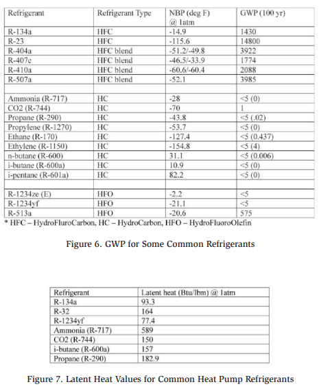
GWP of a refrigerant is a measure of its total contribution to the global warming, resulting from the emission of one unit of refrigerant compared to one unit of carbon dioxide, over a defined time horizon (typically 100 years). Carbon dioxide has GWP of 1. R-134a has a GWP of 1430. Ammonia’s GWP is zero. One unit of R-134a is as potent as 1430 units of carbon dioxide. GWP of some common refrigerants are summarized in Figure 6.
Freon refrigerants are routinely used for various industrial process cooling applications. Some of these systems can be large and contain freon charge exceeding 200 pounds. The new regulation limits the usage of freon with GWP greater than 150 for industrial process cooling applications with more than 200 pounds of refrigerant charge, and process exit temperature warmer than -22°F (-30°C). The new HFO refrigerants that are compliant with this regulation, i.e. having GWP less than 150 are very expensive and so far, compressor manufacturers have limited experience with these fluids. For those reasons, ammonia refrigerant has become a good alternative for these applications.
The regulation limits usage of freon with GWP above 700 for low temperature applications having process exit temperature between -22°F (-30°C) and -58°F (-50°C). In the past, freons R-507/R-410a have typically been used for these applications. Alternate designs consisting of carbon dioxide/ammonia cascading systems or carbon dioxide condensed against chilled water are being considered for new installations.
Limitations of Carbon Dioxide as a Refrigerant for Large Industrial Applications
Carbon dioxide is a high-pressure refrigerant and is a leading refrigerant of choice in certain commercial applications for environmental and safety reasons. The initial equipment cost is high due to high operating pressure, but it is of interest because of its negligible GWP, low-toxicity, and non-flammable characteristics.
Carbon dioxide can be used as a refrigerant in large industrial process cooling applications in transcritical or cascading systems utilizing secondary cooling loop designs. These systems, typically encountered in the chemical or petroleum refining plants are usually large with compression power in hundreds or thousands of kilowatts, and a very high refrigerant charge compared to commercial applications. Due to the size of the facilities, they currently face cost and technical challenges. The size of these systems demands large machinery. The use of oil flooded screws, which are commonly used for refrigeration applications is limited due to the high vapor pressure of carbon dioxide with discharge pressures ranging between 1,250 psig and 1,500 psig (85 barg to 100 barg). Large reciprocating and centrifugal compressors have been considered as alternatives, but the usage of this type of machinery increases project costs and duration. Additionally, the machinery flexibility for head pressure control and turndown are key components in selecting the machinery for the refrigeration applications. The reciprocating or centrifugal machinery is suitable but provides for limited operational flexibility.
In general, due to the high vapor pressure nature of carbon dioxide, these refrigeration systems need special considerations during equipment shutdown. Upon shutdown, the system pressure will increase because of ambient heat gain – and sufficient expansion volume, secondary refrigeration system, or atmospheric vent provisions are required to maintain system pressure below design MAWP. Obviously, if venting occurs, the system will have to be re-charged prior to startup.
Additionally, the system operating envelope needs to be taken into consideration due to high triple point and low critical point of carbon dioxide. Triple point of carbon dioxide occurs at 75.5 psia (5.2 bara) and -69.9°F (-56.6°C). At 1066 psia (73.5 psia) and 87.8°F (31°C) is carbon dioxide’s critical point. Dry ice or solids will form when pressure of liquid carbon dioxide falls below its triple point pressure. Dry ice will block the flow liquid flow paths, plug the orifices, etc. The carbon dioxide evaporators will have to operate at temperatures above the triple point. On the other hand, low critical pressure and temperatures will force carbon dioxide refrigeration systems’ discharge side to operate in a supercritical region at elevated pressures if typical cooling mediums such as air or cooling water is used for condensing or discharge gas cooling purposes.
Ammonia and Carbon Dioxide Heat Pumps
Refrigeration systems are used for cooling purposes in residential, commercial, and industrial applications. A typical system is a closed loop-design, utilizing a variety of refrigerants as working fluids. A simple system consists of an evaporator, a compressor, condenser, and an expansion device. Cooling is achieved by removing heat in the evaporator. The heat absorbed by the refrigerant in the evaporator is then rejected into the atmosphere or another cooling medium in the condenser. The system performance is evaluated on Coefficient of Performance (COP) basis defined as a ratio of useful output to energy input. For refrigeration systems, COP is the ratio of evaporator duty to compression equipment power input. It varies typically between 1.2 and 4.5 depending on the application, which is equivalent to the range between 4 and 1 expressed in terms of horsepower per ton of refrigeration, which is a unit commonly used in North America.
A heat pump is a refrigeration system used for heating purposes. The heat rejection capacity in the condenser is the measure for heat pump performance. The system design and functionality are the same as a closed refrigeration system with the choice of refrigerants. Various heat sources are used for heat input in the evaporator to extract useful heat at the condenser. COP for the heat pump is the ratio of heat extracted at the condenser to the compressor power input. The typical range for COP for the heat pump applications is between 3 and 5.
Ambient air, surface/ground water, or geothermal sources, along with waste heat in industrial settings are used as heat sources for heat pump applications. The heat rejected at the condenser is then used for residential and commercial space heating, industrial processes, or district heating.
The heat pumps in residential and commercial applications are relatively small and designed to have dual cooling and heating functionality. The system design has provisions to reverse the system operation. In a residential setting, the system will work for space cooling in the summer months, by absorbing heat in the evaporator (i.e. provide cooling) and rejecting the heat in condenser. During winter months, the system will work for space heating by reversing the evaporator and condenser roles. The condenser will absorb heat from the heat source and reject heat at the evaporator (i.e. provide heating). A good example of this application would be a geothermal heat source used for heating in the winter. In the summer, heat of compression would be dissipated into the ground.
Heat pumps are also applied to large district heating applications. Freons were traditionally the refrigerant of choice for these applications. Synthetic refrigerants are non-flammable. However, the traditional freon refrigerants have high GWP and are not very efficient. With recent environmental regulations and increased focus on energy efficiency, the natural refrigerants like ammonia, carbon dioxide, and hydrocarbon are being considered for the district heating applications.
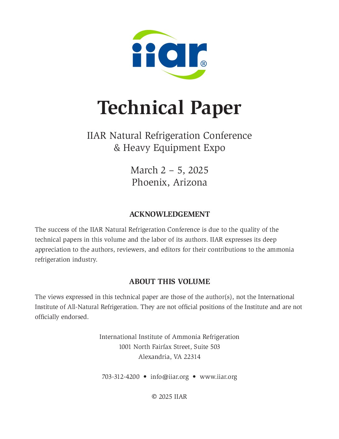
Ammonia and carbon dioxide have become popular because of their inherent advantages. Ammonia is an environmentally friendly refrigerant with zero GWP and zero Ozone Depletion Potential (ODP). It is widely available, and inexpensive. Ammonia has high latent heat and the heat rejection capacity for unit quantity is significantly higher than other refrigerant options. The district heating applications can be quite large, often exceeding 20 MW (5,700 tons of refrigeration) capacity. These will need large proven machinery to provide a reliable solution. The fertilizer industry routinely uses large machinery in ammonia service, and this expertise is being applied to large heat pump applications. Typically, centrifugal compression equipment would be employed. Due to the type and size of the machinery and the associated shaft sealing technology, there is a continuous loss of refrigerant from the system. The cost of ammonia make-up, however, is quite low compared to freon or other refrigerants. The downside of using ammonia in large industrial applications is the additional regulatory requirements if the ammonia charge exceeds 10,000 pounds (4,500 kg). If the system charge exceeds this limit, special operational and training requirements are required. But the efficiency gains and environmental compliance will provide enough benefits to compensate for additional regulatory requirements in large applications.
Carbon dioxide as a refrigerant is environmentally friendly, low-toxic, non-flammable, abundantly available, and cost effective. Carbon dioxide has a high polytropic index resulting in higher temperature for the equivalent compression ratios, which makes it ideal for high temperature heat pump applications. Due to low critical temperature, the system is typically designed to operate in transcritical mode. The machinery selection for such design will be key and must be a proven solution. Carbon dioxide compression expertise in industrial gas and fertilizer industries has been applied to provide large machinery for the large carbon dioxide heat pump applications. Due to the high temperature and pressure, the system design will need components suitable for high pressure and temperature applications. However, the efficiency gains and environmental impact advantages, just like in the case of ammonia, make it a good alternative to other refrigerants. Carbon dioxide heat pumps can also be designed for large differential temperature between heat source and heat use.
Latent heat values for refrigerants used in heat pump applications are listed in Figure 7.
Conclusion
Globally, society and governments are focused on minimizing environmental impacts of industrial activities, and the search for alternate energy sources is underway in a growing number of nations. The refrigeration industry must be a partner in these developments. Natural refrigerants help feed the world population, create new business opportunities, and are more environmentally friendly than the synthetic refrigerants that have been relied on in the past.