


2025 Technical Paper #5
CO2 Heat Pumps: System Solutions and Applications Mapping
Author: Ivan Rangelov, Industrial Heat Pumps Business Development Manager, Danfoss (6000 Kolding, Denmark), Mazyar Karampour, Sustainable Applications Expert, Danfoss (111 64 Stockholm, Sweden) , Thomas Lund, Industrial Refrigeration and Heat Pumps Expert, Danfoss (6000 Kolding, Denmark)
Abstract
CO2 is an emerging refrigerant in North America, but identifying its suitable applications can still be challenging. In Europe, CO2 has been used in heat pumps for several years. This paper discusses the experience of using CO2 in heat pumps in Europe, giving the basics of its use as a refrigerant, such as system solution layouts, opportunities, limitations, and critical factors.
We also benchmark CO2 against other natural refrigerants, including NH3 and R290. The paper aims to support benchmark technologies and indicate which technology may be more suitable for different boundary conditions, such as lift, water return temperature, and source temperature. The optimum heating control strategy is also discussed.
Introduction
CO2 refrigeration has significantly advanced over the last 40 years. After the reinvention of CO2 refrigeration technology in the 1990s, its use expanded in the 2000s, with subcritical systems used as the first stage in a cascade becoming popular in industrial refrigeration (IRF), and transcritical systems becoming common in food retail stores (supermarkets).
The growth in Europe over the past decade has been rapid. In December 2023, there were nearly 72,000 transcritical CO2 systems (68,500 in supermarkets and 3,300 at industrial sites), compared with 29,000 in 2020 and 40,000 in 2021, corresponding to an average annual growth rate of 30-40%. In contrast, there were in total about 3,400 transcritical CO2 systems used in food retail stores and industrial sites in North America in December 2023, although this was an 80% increase from the previous year [1].
Over the past decade, CO2 transcritical systems have increased in size, driven by larger compressors and developments in valve technologies. The cooling capacity of commercial transcritical racks has increased from 100-150 kW (340-510 kBTU/hr) to 2.0-2.5 MW (6,800-8,500 kBTU/hr), and these systems are now being used for both refrigeration and heat pumps (HPs) in large-scale industrial applications. Although transcritical CO2 systems have not yet penetrated the North American market to the same extent as in Europe, rapid growth has been forecast, as indicated by the annual growth in the number of new installations. Drivers for this growth are:
- The AIM act in the US has targeted a decrease in HFC use of 85% by 2036 and a transition to next-generation, more environmentally friendly technologies in heating, ventilation, air conditioning, and refrigeration and HPs [2].
- CO2 is a natural refrigerant with an ozone depletion potential of zero and a global warming potential of one. It is also nontoxic and nonflammable, making it a preferred refrigerant in densely populated areas, where other refrigerants may be unsuitable.
- CO2 is a very efficient refrigerant under certain conditions.
This paper focuses on CO2 HP systems. It presents some experiences of typical CO2 industrial HPs in Europe, identifies critical factors for the use of CO2 in HP applications, describes the application mapping of CO2, and benchmarks its coefficient of performance (COP) against other technologies.
Typical basic layouts of CO2 heat pumps
This section reviews a few of the basic layouts of air-to-water CO2 HPs used in industry, along with the main components. The same layouts are applicable to waterto-water solutions.
Note: The presented layouts are basic and illustrate the system architecture and main components. COPs are given only for illustrative purposes for the compressor used under the given assumptions. Simulations are performed for Compressor Type 1 [3] . For an accurate COP, factors such as the heat exchanger selection, control logic, and defrost method must also be considered.
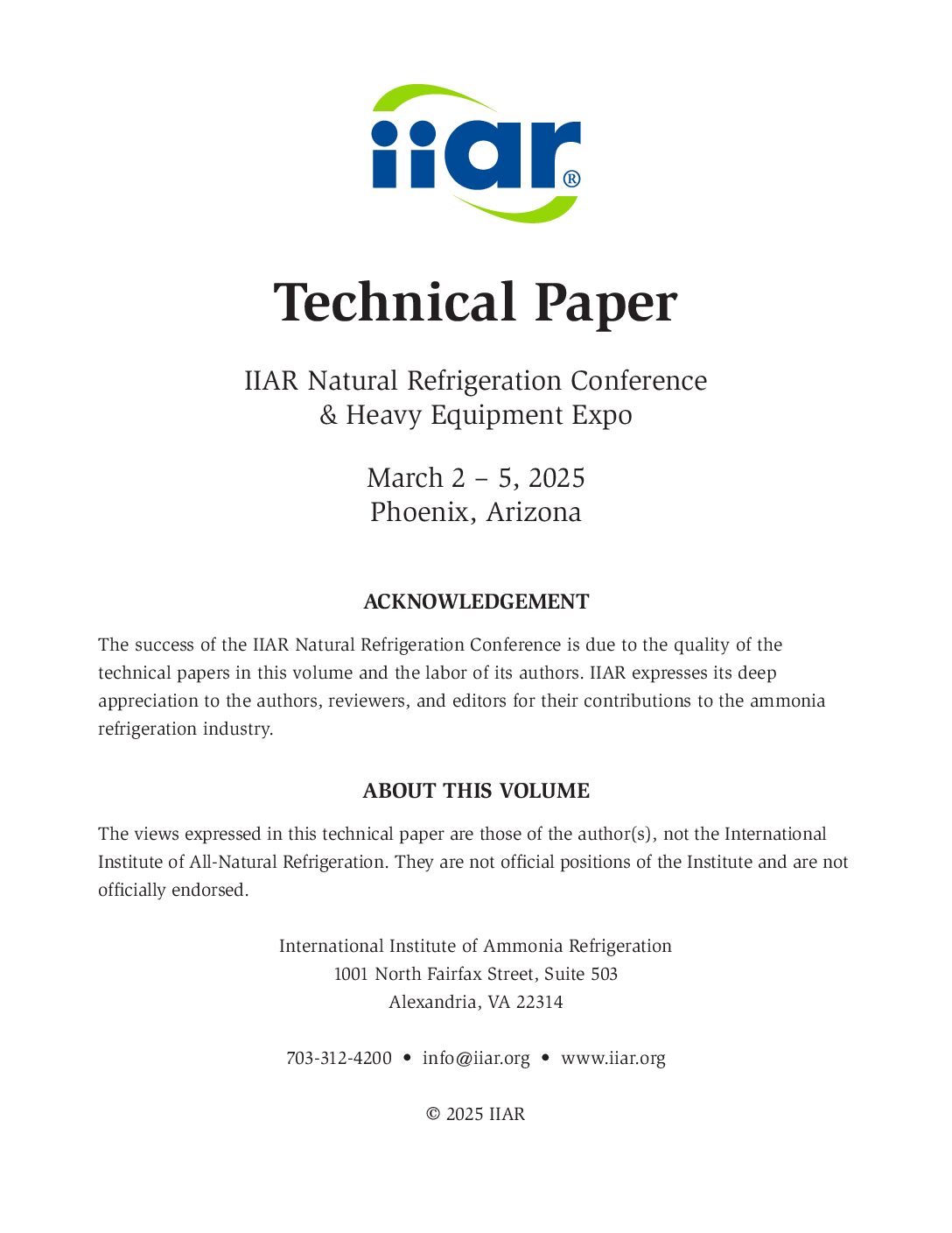
Simple CO2 heat pump (reference):
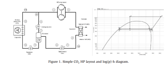
Figure 1 shows the simplest CO2 HP layout, along with its COP, serving as a baseline for comparison with other layouts. It is a one-stage CO2 system consisting of a compressor(s), gas cooler, high-pressure valve (HPV), IT receiver, gas bypass valve, and expansion valve, which typically feeds a Dx evaporator using outdoor ambient air as a source. To obtain COP, we assume:
- Saturated suction temperature (SST) = −2°C (28.4°F); superheating TSH = 10 K (1°F)
- Gas cooler pressure = 110 bar (1600 psi) and CO2 temperature outlet = 40°C (104°F)
- Water: Tin = 35°C (95°F); Tout = 80°C (176°F) • ∆t (pinch) evaporator and condenser = 5 K (9°F)
Under these conditions, COP heating of a semi-hermetic piston compressor is 2.96 [4].
Simple CO2 heat pump with internal heat exchanger
CO2 compressor manufacturers require a minimum superheat of 10 K (18°F) before compressor suction. There are two ways to achieve this.
- Suction regulation: Reduce the saturated suction pressure below the required suction from the source. This is a common method but requires additional compressor power and reduces efficiency.
- Superheater/internal heat exchanger (IHX): Mainly used in CO2 refrigeration, where additional superheat is required. This approach improves efficiency by increasing the required SST due to the lower evaporator superheat.
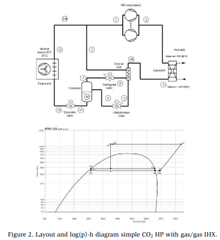
CO2 heat pump with IHX and parallel compressor
Figure 3 presents a system whose efficiency has been further improved by adding a parallel compressor. This compressor’s role is to maintain the IT receiver pressure by removing the flash gas resulting from the pressure reduction through the HPV. Installing a dedicated compressor for this purpose may seem unconventional, but it provides a significant energy benefit by compressing the flash gas at a higher suction pressure compared with sending it to the MT compressor suction. Studies have demonstrated that a system with a parallel compressor can have 7% greater efficiency during transcritical operation compared with a standard CO2 cycle (reference) [5].
For the assumptions in the reference scenario, COP for this layout is expected to be approximately 3.17.
CO2 heat pump with IHX, parallel compressor, and high-pressure lift gas ejector
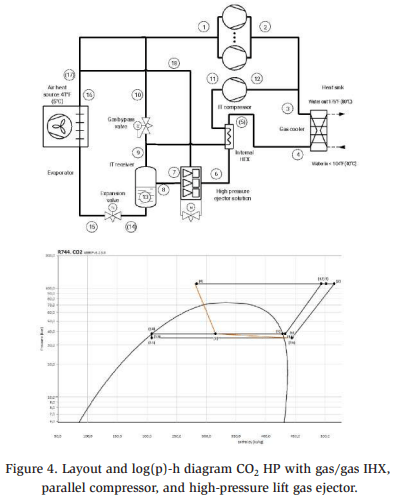
Another possible upgrade to the layout is shown in Figure 4, where a high-pressure lift gas ejector has been added. This is a typical layout for an industrial CO2 HP larger than 500 kW (1,700 kBTU/hr) in Europe. In this example, the ejector, driven by throttling gas from the gas cooler to the IT receiver, extracts gas from the MT (source evaporator) level, mixes it with gas from the gas cooler, and discharges it into the IT receiver (parallel compression suction level). In other words, the high-pressure ejector unloads the MT compressor line, sending more flash gas to the (higher) IT level. According to European CO2 rack manufacturers, the efficiency of a highpressure ejector system with a lift of up to 14 bar (203 psi) is 5% greater than that of the parallel compressor system in the previous example [5]. Based on the compressor COP in the reference scenario, this corresponds to an expected COP heating of 3.33.
CO2 heat pump with low-pressure lift gas ejector
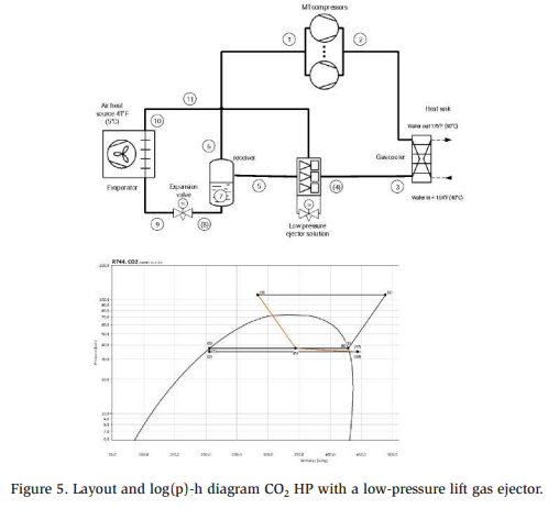
Finally, a low-pressure (LP) ejector can also be used in a transcritical CO2 system, as shown in Figure 5. In this layout, only one compressor suction group (MT level) removes the gas from the receiver. Instead of using a dedicated compressor for the evaporator, all the flow from the evaporator is directed to the ejector, where it is mixed with the gas from the gas cooler and then discharged into the receiver. Liquid is fed from the receiver into the evaporator, and flash gas is directed back to the compressor(s). An LP ejector system with a 5 bar (72 psi) lift can achieve approximately 4% higher efficiency than a parallel compressor system [5]. Based on the compressor COP in the reference scenario, this corresponds to a COP of 3.3.
This configuration is typically used for smaller transcritical system designs of 100-300 kW (340-1,000 kBTU/hr). However, the development of larger ejectors has enabled this layout to be used for systems with higher capacities. Some manufacturers have already assessed and demonstrated LP ejector layouts for MW-scale CO2 HPs [6].
Critical factors for CO2 heat pump applications
Importance of water return temperature
The water return temperature is a key factor determining CO2 HP efficiency. While minimizing the return temperature is always recommended for HP applications, it is critical for CO2 systems. A water return temperature above 45°C (113°F) results in a poor COP and limits the viability of using CO2 as a refrigerant in HPs. This is because throttling from the transcritical operation of the CO2 generates a significant amount of flash gas, typically 50%-55% gas quality for expansion from 110 bar (1600 psi) and 40°C (104°F). A higher water return temperature reduces the system efficiency and compressor capacity, as illustrated in Figure 6.
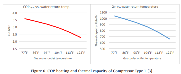
The data in Figure 6 were calculated for a Compressor Type 1 [3] transcritical CO2 compressor with a fixed SST of −2°C (28.4°F), gas cooler pressure of 110 bar (1600 psi), superheating of 10 K (18°F), and gas cooler CO2 outlet temperatures from 25°C (77°F) to 50°C (122°F). The figure illustrates that both efficiency and capacity are severely impacted for a relatively slight increase in the gas cooler CO2 outlet temperature.
Therefore, the water return temperature is a critical factor when choosing a CO2 HP; if the temperature exceeds 40°C (104°F), then it is difficult to justify the use of CO2. Hydronic systems must be designed to keep the water return temperature as low as possible. This can be achieved by preheating cold water for other processes or for domestic hot water (DHW). If this is not possible, then mechanical cooling can be introduced. Mechanical heating is employed by some European manufacturers when the water return temperature in the district heating network exceeds 45°C (113°F) and cannot be reduced. In contrast, if the water return temperature is in the range of 15°C (77°F) to 35°C (95°F), then CO2 HPs can operate with high efficiency.
Higher-temperature source
The COP of an HP generally improves with increasing SST, and in most cases, experts would say, “the higher, the better.” However, due to the specific characteristics of CO2, particularly its low critical point of 31°C (88°F), this is not always true when the source temperature is high enough to push the compressor beyond its operational limits. In such cases, suction regulation at the evaporator is required, which limits the maximum allowable SST. As a result, the compressor cannot fully benefit from a higher-temperature source.
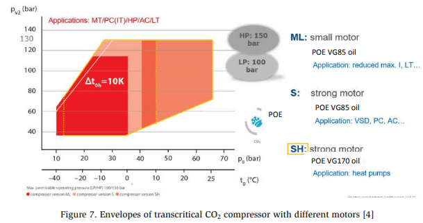
A higher SST for a compressor motor is typically in the range of 18°C (64°F) to 20°C (68°F). However, some manufacturers have implemented compressors with more powerful motors, which have increased the maximum SST to 25°C (77°F). For example, Figure 7 shows the operating envelope for specially designed compressor range for Transcritical CO2 applications, equipped with a strong (SH) motor specifically designed for HP and parallel compressor applications. [4] This is an important note, as this envelope allows for higher suction levels than those in standard models. It sometimes is a challenge to harvest higher temperature source in CO2 heat pumps since there can be a limit on the suction side which means that a suction regulation may be required, which limits the efficiency of the compressor.
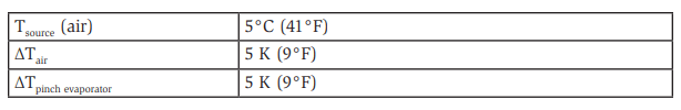
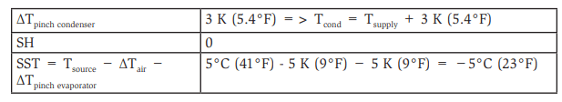
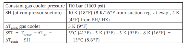
To evaluate the impact of a higher SST, the performance of a Compressor Type 2 [7] was simulated under the following conditions:
- Constant gas cooler pressure of 110 bar (1600 psi)
- TGC out = 40°C (104°F) • SH = 10 K (18°F) at compressor suction, where 8 K (14°F) is from suction regulation at the evaporator and 2 K (4°F) is from the example IHX
- dTair = 5 K (9°F); Tpinch = 5 K (9°F)
In a standard CO2 semi-hermetic piston compressor, the max SST is 18-20°C (64- 68°F). However, as shown in Figure 7, compressors designed for CO2 HP applications can reach a maximum SST of 25°C (77°F). This higher temperature can improve the efficiency compared with a standard compressor, as illustrated in Figure 8.
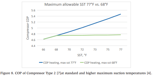
The COPs of both compressors improve with increasing SST, but for the standard compressor, this improvement stops at 20°C (68°F) due to suction regulation, even if the source or vessel temperature continues to rise. In contrast, the compressor with an SH motor benefits from the extended envelope, with its COP improving up to an SST of 25°C (77°F). Note that as the evaporation temperature rises, the compressor capacity also increases but the discharge temperature decreases. This means that attention should be given to the achievable heat recovery temperature when there is variation in the suction temperature.
In summary, compressors with extended envelopes for higher suction pressures are beneficial in HPs with higher source temperatures, as well as in parallel compressors or LP gas ejector systems, where the vessel pressure is generally higher than the evaporator pressure. In the above example, the compressor efficiency is up to 15% higher for the SH motor [4].
Supply and water return temperatures (temperature lift)
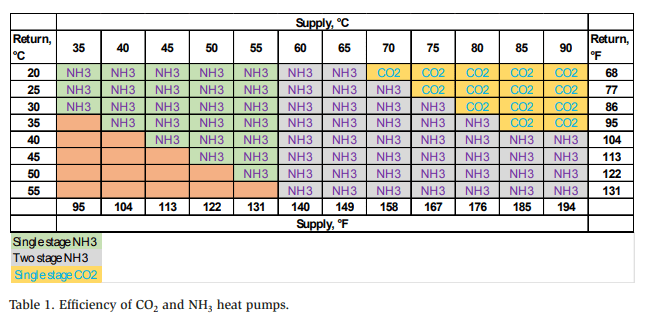
It is difficult to compare the efficiency of different HP technologies, especially at the system level, with results strongly dependent on the assumptions made. Table 1 provides a tentative comparison of COPs. COP is given for NH3 and CO2 HPs as a function of water return temperature and water supply temperature. Note that this comparison is only valid for the assumptions outlined below.
• Generic assumptions: all scenarios
The COP calculations for both systems are based on compressor COPs with the specific assumptions described for each technology below, rather than a complete system simulation. For a fair comparison, a complete system would be simulated, including all component selections, load profiles, and control logic. The source was ambient air at 5°C (41°F). The uncertainty was assumed to be within 5%.
No defrost was considered for the case of an air-cooled evaporator.
• NH3
The simulation was performed for a Compressor Type 3 [8]. We considered a onestage system inside the compressor envelope, but when the lift was too high for a one-stage system, a two-stage NH3 closed system with a liquid temperature of 2 K above the interstage temperature was considered.
Optimizations: System with subcooler, using return water to subcool the condensate. Subcooler with efficiency of 60%: ΔTSC = 60% × (Tcond − Treturn).
• CO2
The simulation was performed for a one-stage system with Compressor Type 1 [3]
COP was optimized for a according to [9] with parallel compression and a highpressure ejector:
- Parallel compression: COP gain +7%
- High-pressure ejector: COP gain +5% (on top of parallel compression)
Important note: Some CO2 HP manufacturers use a significantly lower evaporator superheat than that assumed in this study-often 3-5 K (5-9°F)-and heat exchanger pinch may also be closer, such as 3 K (5°F). As a rule of thumb, very finely tuned CO2 HPs can have a pinch of 7-10 K (5-18°F) between the air source and the SST. For these cases, the “diagonal” between CO2 and NH3 systems will be significantly lower in favor of CO2 than in the example in Table 1.
Table 1 indicates the conditions under which CO2 or NH3 has a higher COP for the assumptions given above. The results are illustrative and should be considered only in the context of these assumptions. The simulations were conducted using compressor manufacturers’ selection software, and a full system model is required to obtain a complete picture. For practical reasons, the calculations were performed with these assumptions, which are considered sufficient to provide a snapshot of the performance of CO2 and NH3 HPs under certain conditions. The following conclusions can be drawn:
- CO2 can be more efficient for higher temperature lifts-when the difference between the supply and return temperatures is greater.
- A control algorithm may improve CO2 HP efficiency by optimizing the gas cooler pressure rather than fixing it at 110 bar (1600 psi). The optimal gas cooler pressure depends on both the water supply and water return temperatures. The optimum control will be explored in our future publications.
- NH3 has a higher COP at lower temperature lifts and when the return temperature exceeds 40°C (104°F).
- CO2 HPs require advanced energy-saving features (IHX, parallel compressors, ejectors) to compete with NH3 HPs in terms of COP. For NH3, the design should allow for a sufficiently large subcooler.
- For the selected conditions, a one-stage system can be used for CO2 HPs. However, NH3 HPs may require a two-stage system to supply water above 55°C (131°F), increasing the complexity, investment cost, and operation cost.
- In practice, CO2 HPs with semi-hermetic piston compressor racks seldom deliver water above 80°C (176°F), even though temperatures of up to approximately 90°C (194°F) are feasible if the water return temperature is sufficiently low.
- Note also that compressor capacities vary considerably-by as much as fivefold-for CO2 compressors within the given return temperature range.
Despite the importance of COP, designers must also consider other factors, such as refrigerant acceptance and risk assessment. In Europe, CO2 HPs are generally permitted in populated areas, whereas there are stricter regulations for NH3 HPs. The total cost of ownership (TCO) must also be assessed, which includes the initial investment and the service costs over the equipment’s lifetime. The availability of servicing and equipment must also be considered. Furthermore, fluctuating energy prices from renewables, such as wind turbines, might influence the choice of HP if it can only operate at times with low energy prices.
In summary, no single HP technology is the most efficient, with CO2 and NH3 HPs each being more suitable for specific conditions, applications, and locations.
Basic applications: mapping heat pump technologies
This section compares several HP technologies and outlines some key technical requirements influencing the selection of the technology, including COP and compressor swept volume. The analysis is based on a simulation of several technologies, as summarized below, and compressor COPs for the assumed operating conditions. Table 2 gives the assumptions and brief descriptions of the systems studied.
It is critical to note that the following results are valid only for the specific assumptions and tools used in this analysis, which are based on the authors’ experiences and the tools available to them. To compare such technologies for a real system, a detailed simulation model must be developed that considers not only the compressor COP, but also the type and size of heat exchangers, control strategies, losses from pipes and components, and other factors.
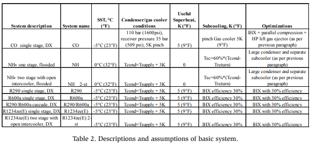
Notes on assumptions
- Field experience with NH3 HPs indicates that they usually have a separate subcooler, which is not necessarily the case for other technologies. Therefore, subcooling with 60% efficiency was assumed only for NH3. For other technologies, subcooling was assumed to use an IHX with a fixed efficiency of 30%.
- Experience also suggests that NH3 condensers in HPs often have a lower condenser pinch than for other technologies because of the use of a large amount of superheat from NH3. Therefore, the pinch was assumed to be 3 K for NH3 HPs and 5 K for other technologies.
- The simulations used different compressor tools. For CO2, calculations were performed using VAP for the Compressor Type 1 [3], while other technologies were modeled using manual calculations with a fixed compressor isentropic efficiency of 70%.
Heating COP
An especially important factor in evaluating an HP technology is the heating COP. Figures 9 and 10 summarize the results of the simulations of heating COP for the assumptions in Table 2.
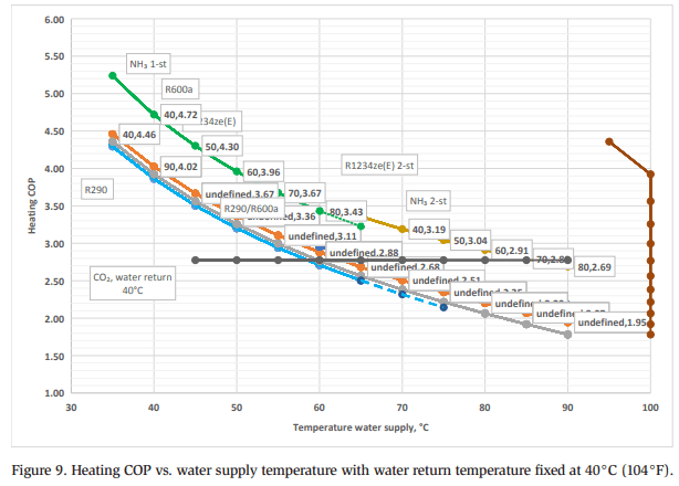
The heating COP curves in Figure 9 were generated for different water supply temperatures, with a fixed water return temperature of 40°C (104°F) for CO2. The other systems are largely unaffected by the water return temperature. The key exception is NH3, for which a dedicated subcooler was assumed. For this system, COPs are shown as averages, whereas for the other systems, the COP remains unchanged due to the lack of a dedicated subcooler. The main observations were as follows:
- COP decreases with increasing water supply temperature due to the higher lift, except for the CO2 system, where COP is not impacted. This is because the water supply temperature can be raised to about 5K (9°F) below the compressor discharge temperature without increasing the gas cooler pressure, thereby maintaining COP.
- The CO2 system is insensitive to the water supply temperature due to the assumed constant pressure in the gas cooler and receiver. In practice, its performance will depend on the optimal CO2 control curve, and hence the COP curve would not be entirely flat. Nevertheless, the assumed values are sufficient to illustrate the trend.
- One- and two-stage NH3 systems are the most efficient in almost all scenarios, followed by R1234ze(E) and R290/R600a. The former system is about 7% more efficient at a lower lift, but this advantage decreases with increasing lift, with comparable performance at a water supply temperature of 90°C (196°F). The other systems have similar efficiencies, although R600a shows slightly superior performance to one-stage 1234ze(E), with 6% higher efficiency at lower lifts and about 10% higher efficiency at higher lifts.
- R290 is the least efficient system, but its COP is similar to that of 1234ze(E) under the conditions where R290 can be used. Current compressor technologies allow a maximum water supply temperature of 65°C (166°F). However, newer scroll compressor prototypes that can reach a temperature of 80°C (176°F) in the condenser have been developed [10].
- • At lower lifts, the CO2 system at a water return temperature of 40°C (104°F) is the least efficient under the assumed conditions up to a water supply temperature of around 60°C (140°F). However, it has comparable performance to NH3 systems at higher lifts, with a breakeven point of about 70°C (158°F). At even higher lifts, such as at a water supply temperature of 85°C (186°F) and above, its COP even challenges that of NH3 systems.
- At a low water return temperature, the breakeven point for CO2 will be at a lower supply temperature. For the assumed conditions, the heating COP is 2.8. If the water return temperature is 35°C (95°F), COP reaches 3.1, an efficiency gain of 12%. In contrast, at a water return temperature of 45°C (113°F), COP decreases to 2.4. This highlights the importance of the water return temperature in CO2 HP systems.
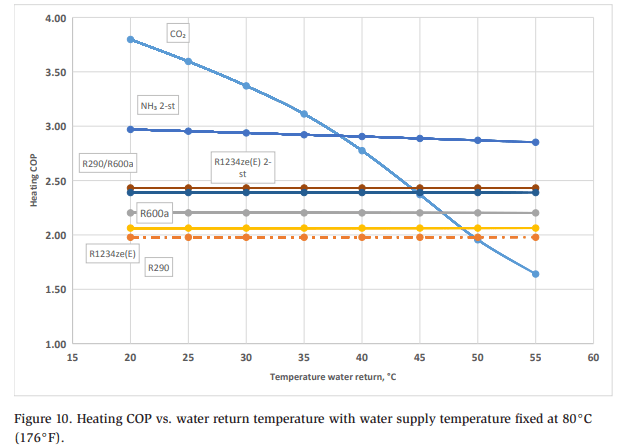
In contrast to Figure 9, Figure 10 shows COPs at a fixed water supply temperature of 80°C (176°F) and various water return temperatures. The key findings are:
- CO2 has the highest efficiency at lower water return temperatures, but its COP decreases rapidly with decreasing water return temperature. For return temperatures exceeding 37°C (99°F), two-stage NH3 is again the most efficient technology. One-stage NH3 is infeasible due to excessive lift, resulting in high discharge temperatures. For other technologies, COP is within the same range as in Figure 9.
- Unlike in Figure 9, COP is relatively stable except for the CO2 system. This highlights the extreme sensitivity of COP to the water return temperature for this system, with a 2%-3% decrease per 1K temperature increase.
- The COP of the other systems remains almost unchanged with increasing water return temperature. The slight decrease in efficiency for NH3 is due to the assumption that NH3 has a dedicated subcooler. For the other systems, subcooling only occurs in the IHX and is therefore linked to suction temperature, which is fixed in this example.
In summary, CO2 is an excellent refrigerant for HPs, with its efficiency under suitable conditions even rivaling the traditionally most efficient technologies. The sweet spot for CO2 HPs is at high temperature lifts and low water return temperatures. If the system requirements are unsuitable for CO2, other refrigerants may be more appropriate, depending on the conditions and environment.
Note that the results for COP are strictly based on the assumptions in Table 2 and should be used only as guidance. To calculate COP for a real system, more sophisticated calculation methods must be applied, such as system modeling with a real load profile, compressor polynomials, heat exchangers, and control logic.
Initial investment
COP is usually the first factor evaluated by HP engineers. However, a complete feasibility study must also consider other factors, including the TCO over the system lifetime. All possible scenarios should be assessed in terms of net present value over the installation lifetime to determine the optimum TCO. Notably, the optimal COP may not always be the best choice if it requires a significantly larger installed compressor swept volume. Efficiency is important, but it is not the only important factor.
However, performing a TCO analysis is complex and often impractical in industry. As a simpler alternative, the required compressor swept volume per installed capacity can be considered as an indicator of the initial investment. This quick comparison includes both the initial investment, such as the size and number of compressors and other components, and the service costs over the equipment’s lifetime. For example, fewer and smaller compressors may require less servicing over their lifetime.
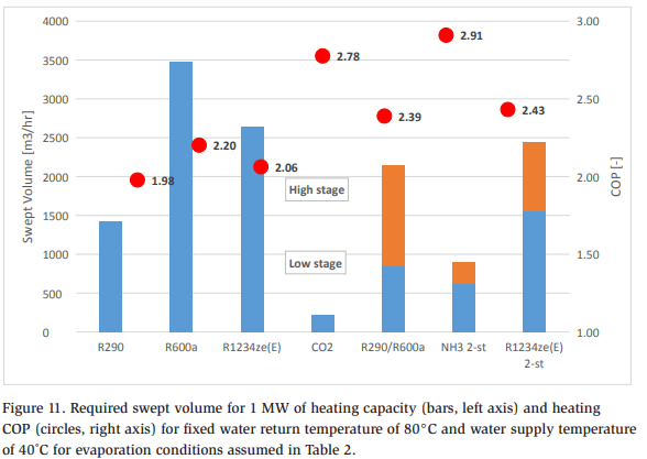
Figure 11 compares the required compressor swept volume (bars, left axis) and COP (circles, right axis) for a thermal capacity of 1 MW (3400 kBTU/hr) for the technologies in Table 2 at a fixed water supply temperature of 80°C (176°F) and a fixed water return temperature of 40°C (104°F). The swept volumes are ideal values that do not account for volumetric efficiency losses, which vary with the compressor. For this study, it is considered sufficient to evaluate the technologies without examining specifics at the compressor level.
The results are summarized as follows:
- CO2 requires the smallest swept volume due to its high suction density; however, this is at the cost of significantly higher design pressure of the equipment. NH3 follows, benefitting from its extremely high specific enthalpy difference over the evaporator. These two technologies require considerably smaller installed volumes than the other technologies. They have the highest COP values for the given conditions, although the differences in COP values among the technologies are smaller.
- Among the hydrocarbon refrigerants, R290 has a higher energy density, requiring a compressor swept volume about 2.5 times less than that of R600a. However, its COP is also lower. An R290/R600a cascade has a higher COP than either refrigerant alone because the compressors can operate at much lower pressure ratios, thereby consuming less total power than in one-stage scenarios. The system COP is comparable to that of CO2 and requires a total swept volume between those of CO2 and a one-stage hydrocarbon system.
- The performance of one-stage 1234ze(E) is similar to that of R600a, and it also requires a lower compressor swept volume. Two-stage 1234ze(E) with an open intercooler has about 20% higher heating COP and slightly lower total swept volume than the one-stage system. Again, this improvement is due to the lower pressure ratios for the compressors in each stage.
In summary, in addition to COP, the required swept volume should be considered when evaluating HP technologies, which indicates the size and number of compressors and other components, as well as expected lifetime service costs. Note that the installed swept volume of 1 m³/h for CO2 is higher than that for hydrocarbons or HFOs due to the higher pressure requirements of the equipment.
Conclusions
This paper has discussed the fundamentals of HPs using CO2 as a refrigerant, including basic layouts and critical factors for this technology, with examples given. Additionally, CO2 has been benchmarked with several other HP technologies for specific operation conditions to demonstrate where it may be the preferred option or unsuitable.
CO2 can be an excellent refrigerant for HP applications under the right conditions, particularly when the water return temperature is low and a high temperature lift is required.
The performance of CO2 HPs can be optimized in multiple ways. For example, a fine-tuned system architecture incorporating IHXs, parallel compression, and ejectors can improve COP by about 12%. Additionally, in the case of relatively hightemperature sources or parallel compressors, an extended compressor envelope that allows operation at higher suction pressures can enhance performance by up to 15% compared with standard compressors.
Although various refrigerants can be used in HP applications, the unique feature of CO2 is its efficiency at high lifts. However, it is sensitive to the water return temperature, with the efficiency rapidly decreasing at higher temperatures. These characteristics contrast with those of the other refrigerants considered in this paper.
Finally, although most engineers compare HP systems almost exclusively in terms of COP, we argue that other factors should also be considered. These include lifetime TCO, regulatory requirements, availability of servicing and technology, future-proof technology selection, skilled personnel, experience, and risk assessment. However, calculating TCO for each project is complex and often impractical for industry. A more feasible approach is to estimate the initial investment cost of the HP and the service cost by comparing the compressor swept volume required per unit of installed heating capacity for different systems.
This paper has not addressed optimized control and the impact of evaporator superheat. Instead, conservative values were used for CO2 evaporator superheat and pinch. Similarly, gas cooler pressure was set conservatively, as is common in industry. However, the industry is moving toward optimized solutions for CO2 that minimize evaporator superheat and incorporate control logic for optimizing the gas cooler and receiver pressures. These aspects will be studied in our future work.
References
[1] ATMOsphere, “2023 ATMOsphere Market Report,” ATMOsphere, 2023. [2] EPA, “Background on HFCs and the AIM Act,” 07 07 2024. [Online]. Available: https://www.epa.gov/climate-hfcs-reduction/background-hfcs-and-aim-act. [3] Danfoss Bock Transcritical CO2 compressors, Bock compressor HGX56/680-4SH CO2T 50 Hz, https://vap.bock.de/stationaryapplication/Pages/Index.aspx, 2024. [4] Danfoss Bock Transcritical CO2 compressors, “vap.bock.de,” 2024. [Online]. Available: hhttps://vap.bock.de/stationaryapplication/Pages/Index.aspx. [5] K. G. Christensen, in CO2 varmepumper fra Fenagy A/S, 2021. [6] P. Clardy, Interviewee, Danfoss CO2 Ejectors for Industrial Applications. [Interview]. February 2023. [7] Danfoss Bock compressors, Bock HGX46/345-4SH CO2T 50Hz, https://vap.bock. de/stationaryapplication/Pages/Index.aspx, 2024. [8] JCI Comp 1 software, Sabroe HPX 708 piston, Comp 1 software, 2024. [9] K. Christensen, “Technical experiences from operating large CO2 heat pumps,” in Køle og varmepumpeforum 2023, Copenhagen, Denmark, 2023.