NDT Methods for the Ammonia Refrigeration Industry
By Jim Kovarik, Gamma Graphics Services
In other industries, insulation is installed to protect people from touching hot process piping and getting burned; or to keep heat in the pipe to assist in lowering the viscosity of the process fluid thereby facilitating flow. If water comes in contact with hot piping, it will evaporate quickly or boil-off immediately, and therefore, corrosion under insulation is not a great concern. The ammonia refrigeration industry is markedly different from other industries. In the ammonia refrigeration industry, insulation is installed on piping to prevent the pipe from absorbing heat. Because refrigeration piping is generally cold, water vapor will condense on it if given an opportunity. Any water that condenses or comes in contact with the pipe through some other means will not readily evaporate or boil-off, but becomes trapped in the insulation. Three things necessary for corrosion under insulation (CUI) are: water, unprotected metal, and oxygen. If the temperature of the pipe is ever above 32°F, then the conditions are ripe for corrosion to occur. If the pipe experiences thermal cycling (freezing then thawing, then freezing again), the rate of corrosion actually increases. This is due to the fact that ice expands and will flake-off larger sections of metal exposing bare metal underneath. When the ice thaws, the water will flow into the newly created fissures left behind by the ice and begin to corrode the fresh metal surfaces. When the pipe freezes again, the water will form ice which flakes even more metal away from the rest of the pipe and the process continues until the pipe eventually fails.So, how can we find out if CUI is occurring? NonDestructive Testing (NDT) is comprised of many different methods and techniques that will not harm the object being tested. Of the dozens of nondestructive inspection methods available, only a few are applicable to identify corroded
areas on insulated piping. Most of these involve some removal of insulation in order to inspect the pipe.
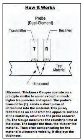
The most common NDT method is ultrasonic thickness testing (UTT). The basic physics of ultrasonic thickness testing involves the fact that sound travels at very specific velocities in different materials (Fig. 1). Sound travels much slower in ice than in steel. Sound travels very slowly in air – that is why you can see a lighting strike before you hear the thunder. The ultrasonic instrument measures the time it takes sound to enter a material (in this case the pipe), bounce off the inside wall of the pipe and return to the transducer. The time it takes to make the round trip is multiplied by the velocity of the sound in the material (steel), and the result is the total distance that the sound traveled. In other words, the ultrasonic instrument converts time into distance. The speed of sound in ice at 0° C is 1402 M/s and the speed of sound in steel is more than four times as fast at 5790 M/s. Because sound travels so poorly in air, a couplant, or medium is used to “couple” the transducer to the pipe. This couplant is compressed so that a very thin layer is present between the transducer and the pipe which facilitates sound transmission, but does not change the thickness measurement. In most cases, the couplant is a water-based gel. UTT on ammonia piping and vessels is accomplished by removing a plug in the insulation and placing a transducer on the pipe through the hole. Unfortunately, many NDT technicians perform UTT on piping and vessels at refineries or utility plants where the pipe and vessels are at or above ambient temperatures. In cold applications where the temperature is below freezing, the water-based couplant can, and will, freeze on the pipe. This can mean that the ultrasonic instrument will display an erroneous thickness reading. For example, if a water-based couplant is placed on a transducer and then applied to a pipe below 0° C, and the couplant freezes before it is fully compressed so that a 0.060″ layer of ice exists between the pipe and the transducer, the ultrasonic instrument will display a value of approximately 0.250″. This is because the instrument is calibrated for measuring steel and will use the sound velocity of steel applied to the thickness of the ice layer. Because the velocity of ice is more than 4 times slower than steel, the ultrasonic instrument will show 4 X 0.060″ = 0.240″. This same scenario can also occur if ice is already present on the pipe, but the technician cannot see the ice through the drilled hole in the insulation. The technician will dutifully record his “pipe wall thickness” and move to the next location. Another factor that impacts the reliability of the UTT method is the surface condition of the pipe. If the pipe has rust scale on it, the scale will act much like the ice example. If the surface of the pipe is pitted, then the face of the transducer cannot be positioned so that it is flat with the pipe wall, and either no data will be displayed or erroneous data will be obtained. A technician experienced in the ammonia refrigeration industry will be able to avoid the issues mentioned above and will be able to properly obtain reliable UTT thickness data.
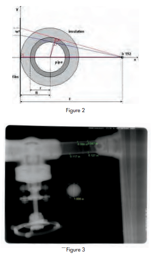
A second common NDT method is Radiographic Testing (RT). This technique may be further defined as conventional (uses x-ray film), Computed Radiography (CR) (uses an imaging plate in lieu of film), and Real-Time Radiography (RTR) (fluoroscopy). In conventional RT, a source of radiation is used to expose a piece of film just like you would get an x-ray at the doctor’s office. The resulting image would then be analyzed by the radiographer and he would fill out his report. For insulated pipe, the film is placed on one side of the pipe, the radiation source would be positioned a distance away from the opposite side of the pipe, and the area would be evacuated of all personnel before the radiograph was made (Fig. 2). Because of the physics of the method, a comparator (usually a steel ball of a known dimension) is used to adjust the values measured in the completed radiograph (Fig. 3). If the pipe is small, two pipe walls can be measured for thickness in one radiograph. For larger diameter pipe, only one pipe wall may appear in the radiograph. An advantage of RT is that the images are relatively easily understood. A disadvantage is that unless a corroded area is imaged exactly perpendicularly to the radiation beam, it may be analyzed improperly or possibly not even discerned in the radiograph. Computed Radiography (CR) is essentially identical to conventional RT when exposing the image plate in lieu of film. However, the exposed image plate is then developed with software in a computer and computerized analysis tools are available which greatly enhance the applicability of CR over conventional RT. When a radiograph is made, the resulting image is magnified due to geometric circumstances. Notice in Figure 2 that the pipe wall thickness projection is larger on the image than in reality. Therefore, it is necessary to place a comparator (steel ball of known dimension) directly above or below the pipe wall to be measured. As shown in Figure 3, the comparator is used as a calibration standard. The known dimension of the comparator is entered into the software and all subsequent thickness measurements are corrected automatically. On average, approximately 15 to 20 radiographs can be acquired in a day by a radiography crew.
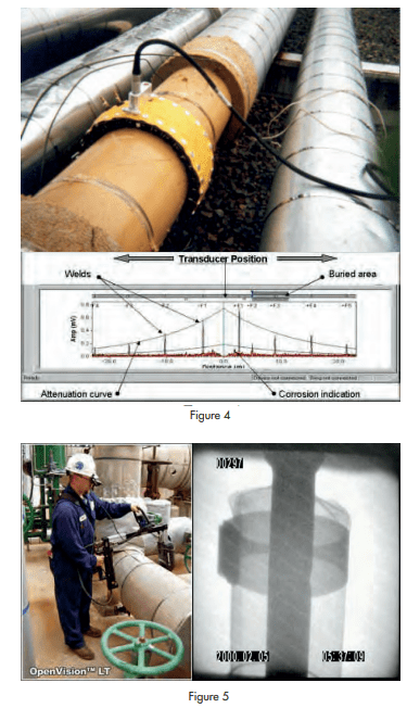
Long Range Ultrasonic Testing (LRUT) is a relatively new technique that allows for the inspection of up to hundreds of feet of piping from a single access location on the pipe (Fig. 4). The benefits are that only a very localized area of the pipe needs to be stripped of insulation. The test is best suited for long straight runs of pipe, and will deliver usable results through 2 butt-welded elbows. This is one of the few tests that can be performed on wall or roof penetrations. However, the ultrasound will not propagate past any flanges, valves, sockolet fittings, or schedule changes in the pipe.
Wet insulation can negatively affect the results of the test by attenuating the ultrasound transmission in the pipe. One of the disadvantages is that the transducer collar will only fit 2 inch diameter pipe and above at the present time. Another is that even though sound travels through “100%” of the pipe material, the sensitivity is approximately 10% to 15% the cross-sectional area of the pipe. In other words, on a 2 inch schedule 80 pipe, a corrosion area larger than 0.150” in the circumferential direction would have to exist in order to be detected. Corroded areas that are oriented along the axis of the pipe having a length of even a few inches but less than 0.150″ in the circumferential direction could be missed entirely.
Fluoroscopy or Real-Time Radiography (RTR) is an NDT method that uses x-rays to “see” through the insulation and jacketing with the image displayed on a heads-up display or monitor. RTR a rapid screening tool capable of identifying areas of wet insulation, check-valves that may have been covered by insulation, weld lines, and rust scale on the surface of the pipe (Fig. 5). However, since it is not capable of penetrating the pipe itself, no pipe wall thickness information is acquired. The RTR operator will identify areas on the insulated piping for additional inspection with other complimentary NDT methods for a more quantitative conditional assessment of the pipe. Figure 5 shows an RTR operator and an image of small diameter piping taken through insulation.
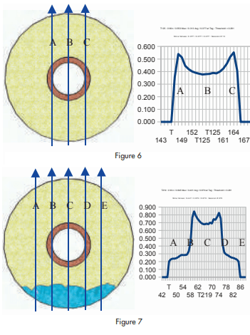
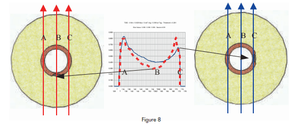
Radiometric Profiling (RP) was specifically designed to assess the integrity of piping through insulation quickly and semi-quantitatively. This technique involves a highly collimated beam of low intensity radiation being directed through the pipe. The total density contributions from the pipe, the product in the pipe, and the insulation are represented as a total steel-thickness graphically on the computer display. This real-time graphical display of density in terms of steel thickness is available to the operator so that he or she can recognize various anomalies that may be encountered. Advantages include the ability to “Slice” across or “Scan” along insulated pipe without having to remove insulation. Pits can be identified and evaluated for metal loss as long as the radiation beam is directed across them. Figure 6 depicts an RP slice conducted across uncorroded pipe and dry insulation. However, very wet insulation is readily discernible in Figure 7. The density contribution of the wet insulation can be estimated and removed mathematically from the final result. Even . if the Profiler is not oriented perpendicularly to the pipe, a slice across the pipe can reveal corrosion as evidenced by the two blue “peaks” of the scan not being of equal amplitude as shown in the diagram to the right in Figure 8. If the corrosion area is in line with the radiation beam, then the results will show a reduction in thickness at “B” as shown in the diagram to the left in Figure 8. The reporting analysis will remove the density contributions from the insulation, any product in the line, and one nominal wall thickness to achieve the calculated remaining wall thickness of the pipe. Unlike Radiography, RP does not require any personnel to be evacuated during the testing and will not impact any other personnel that may be working at the facility at the time of inspection. The limitations of this method are that the line size must be known beforehand, and the largest pipe diameter that may be inspected is 24 inches inclusive of insulation.
All of the methods described in this article are appropriate for use in the ammonia refrigeration industry. No single method can be considered “perfect,” or “all encompassing” as each method has both capabilities and limitations. However, many methods are complimentary to each other and a combination of two or more methods may be employed to obtain the very best results. Technician experience is also a key element that must be considered when having any inspection work performed. Not only should the technician’s NDT experience be considered, but also their experience within the ammonia refrigeration industry. Most NDT technicians will be very capable in using the various inspection methods, but very few will have measurable experience working with piping and vessels below freezing temperatures.


