2024 Technical Paper #7
Application and Considerations for Internal Relief in Industrial Refrigeration Systems
Author: Todd B. Jekel, PhD, PE, and Douglas T. Reindl, PhD, PE Industrial Refrigeration Consortium
Abstract
The requirements for determining the capacity of vapor service pressure-relief devices applied to partially liquid-filled ammonia vessels/equipment and discharging to the atmosphere, as well as liquid service relief devices completely filled with non-volatile liquid (e.g., compressor oil) discharging internally to an ammonia refrigeration system, are provided in IIAR 2 (2021). The requirements for determining the capacity of vapor service and liquid service relief devices for internal relief are less well detailed in IIAR 2 (2021). With the design and application of pressure-relief devices for protecting oil pots and thermosiphon oil coolers intended to discharge internally to refrigeration systems becoming more common recently, there is a need to establish a sizing basis for vapor and liquid service relief devices intended to relieve internally to the system.
In this paper, we provide the applicable background, along with details of a method for sizing pressurerelief devices intended to discharge internally to an ammonia refrigeration system. In addition, we answer questions along the way such as: How does the sizing of a pressure-relief valve relieving internally to the system for non-volatile liquids differ for a volatile liquid, such as a refrigerant? Does this impact the choice of relief device? How does the sizing of a vapor-relief valve discharging internally to a refrigeration system differ from a liquid-relief valve? We present the thermodynamics governing heat addition to a vessel partially filled with liquid refrigerant and highlight the differences in relief-device capacity requirements between the removal of a mass of liquid or vapor to maintain the pressure of the equipment below its design pressure. Methods for analyzing internal relief arrangements using plausible scenarios are presented, along with recommended practices for their installation.
Note: This June 6, 2024 version corrects a minor sign error in equation 11.
Introduction
Pressure-relief valves are the principle means of providing overpressure protection for pressure vessels and other ASME-stamped equipment used in refrigeration systems. The relief valve must be large enough to discharge refrigerant from the pressureprotected component at a rate sufficient to maintain the protected component below its maximum relieving pressure, which is related to its Maximum Allowable Working Pressure (MAWP), based on the conditions anticipated to create the overpressure. The refrigerant discharging from a pressure-relief valve can be directed externally to the system or internally to the system in an arrangement commonly referred to as “internal relief.” Although relief arrangements that discharge externally to the system to the atmosphere are the most prevalent, the use of internal relief has been trending up in the industrial refrigeration industry over the last decade. The two most common applications of internal relief in industrial refrigeration system applications are to pressure protect oil pots and thermosiphon oil–cooling heat exchangers. For thermosiphon oil–cooling heat exchangers, the internal relief is being applied to the refrigerant side (volatile) and the oil side (non-volatile). Here, we focus on considerations of the internal pressure-relief volatile liquid refrigerant and vapor rather than the simpler case of relieving non-volatile liquids.
In order to apply a pressure-relief valve for internal relief, the pressure-protected equipment must have an MAWP higher than the MAWP of the component receiving the mass-flow rate being discharged due to the overpressure of the pressureprotected equipment. As such, activating the pressure-relief valve in an internal relief configuration will occur only when the pressure-protected component is isolated from the system, such as during maintenance, and when subject to overpressure from an external or internal energy source. When the component is not isolated, overpressure protection is provided by pressure-relief valves located elsewhere in the system, those relief valves, ultimately, discharging to the atmosphere or to a treatment system (e.g., a diffusion tank or flare).
With the increased application of internal relief arrangements, there are a number of details that must be properly engineered to ensure the intended level of safety is provided. Some of the arrangements for internal pressure relief result in installations that will not provide adequate overpressure protection or are not compliant with current standards, or both. Although we review the requirements for internal relief found in existing standards, our goal is to provide designers with additional information so they can engineer safe and compliant pressure-relief systems. Recommendations to address gaps or requirements that may be ambiguous in existing standards or codes are provided. Also presented in this paper is a detailed analysis for the capacity determination of pressure-relief valves for the internal relief of volatile liquids (i.e., refrigerants). Methods for analyzing internal relief arrangements using plausible scenarios are presented, along with recommended practices for their installation.
Standards and their Requirements for Relief Protection
We begin by reviewing the key requirements for overpressure protection found in the applicable standards, including ASME for stamped equipment and pressure vessels and IIAR for ammonia refrigeration systems, as well as ASHRAE 15 for historical context. In the remainder of this paper, the term “pressure vessel” applies to any pressure equipment that meets the design, material, construction, and pressure testing requirements set forth in the ASME Boiler and Pressure Vessel Code (BPVC), Section VIII, Division 1.
ASME
In the 2021 edition of the ASME BPVC, many, but not all, of the requirements for the pressure-relief protection of pressure vessels, including relief devices, had been moved to a newly created Section XIII. Section VIII, Division 1 of the BPVC maintains some basic requirements for the overpressure protection of ASME-stamped vessels and equipment. For example, Section UG-150 of Section VIII, Division 1 sets forth the following requirements:
- Relief valves used for protecting pressure vessels must be constructed and certified in accordance with ASME Section XIII.
- All pressure vessels, regardless of size or pressure, must meet all of the requirements in UG-150-UG-156.
- Applies to unfired steam boilers.
- Applies to unfired steam boilers.
- Vessels that are intended to operate completely filled with liquid must be designed for liquid service unless the vessel is otherwise pressure-protected.
- Requirements set forth in Section XIII apply.
Section UG-151 assigns the responsibility of sizing and selecting the relief devices and engineering the balance of the relief system and its installation to the end-user. UG152 requires that:
- The user or the user’s designated representative must identify all potential overpressure scenarios and the method of overpressure protection used to mitigate each scenario.
- The relief device(s) being used for overpressure protection must have sufficient flow capacity to prevent the vessel’s pressure from rising by more than 10% over the MAWP [see also UG-153(a)].
- Vessels interconnected with piping and having no intervening stop valves can be pressure-protected with a single, sufficiently sized relief device.
- Heat exchangers must be protected with a pressure-relief device of sufficient capacity to avoid overpressure in an internal failure were to occur.
- The relief device’s capacity rating must be in accordance with Section XIII.
Additional key requirements in Section VIII, Division 1 include the following:
- UG-155(c) requires selecting a pressure-relief device set pressure that includes the effects of superimposed back pressure. More specifically, the set pressure of a relief device plus the superimposed back pressure corresponding with the design pressure for the component receiving the internally relieving refrigerant cannot be greater than the protected component’s MAWP.
- UG-156(c) requires the inlet connection to pressure-relief devices intended for the relief of compressible fluids to be connected to the vessel in the vapor space above any liquid contained in the vessel. Pressure-relief devices intended for the relief of liquids shall be connected below the liquid level.
- UG-156(d) requires the opening through all pipe, fittings, and non-reclosing pressure-relief devices (if installed) between a pressure vessel and its pressurerelief valve to not be less than the area of the pressure-relief valve inlet. Also, the effects of inlet pressure loss cannot reduce the relief-device capacity below that required or otherwise adversely affect the proper operation of the pressure-relief device.
Most of the contents of the newly created Section XIII of the ASME BPVC relate to the requirements of pressure-relief devices themselves, including their performance characteristics, mechanical design, manufacturing (including assembly and inspection), production testing, and marking. However, Section XIII also includes requirements for their installation, and additional requirements for overpressure protection by system design in lieu of using pressure-relief devices.
- Part 12 of ASME Section XIII includes some relief-device installation requirements. The following highlights the key provisions in Section 12:
- 12.3(e) requires consideration of the inspection, replacement, and repair of the relief devices.
- 12.5 echoes the requirements in UG-156(d), but also states that the design of the inlet line and connection to the pressurized equipment must consider the stresses caused by the discharge reactive forces and static loads from the relief device.
- 12.8(a) states that the pressure that may exist or develop in the discharge piping must not reduce the relieving capacity of the pressure-relief devices below that required to properly protect the pressurized equipment, or adversely affect the proper operation of the pressure-relief devices.
- 12.8(b) requires the design of the discharge vent system and associated supports to consider the stresses caused by the discharge reactive forces and static loads on the relief device.
- 12.8(c) specifies that the discharge lines from pressure-relief devices be designed to facilitate drainage or be fitted with drains to prevent liquid from lodging in the discharge side of the pressure-relief device, and such lines shall lead to a safe place of discharge.
- 12.8(d) requires that, when multiple pressure-relief devices are arranged to discharge through a common stack or vent path, the maximum back pressure that can exist at the exit of each pressure-relief device during simultaneous releases cannot impair the operation or diminish the capacity below that required to simultaneously protect each piece of pressurized equipment.
The above ASME BPVC requirements apply to all ASME-stamped components.
IIAR
IIAR 2-2021 Chapter 15 establishes overpressure protection requirements for ammonia refrigeration systems that are largely focused on the relief of vapor that results from an isolated component that contains liquid and vapor absorbing heat. While internal relief is covered in Chapter 15, the requirements are not developed or detailed to the same degree as the requirements for a vapor service design discharging externally to the system. The following summarizes the key pressure-relief requirements in Chapter 15, differentiating those that are ATMOSPHERIC, INTERNAL or BOTH, as indicated at the end of each given item:
- Pressure-relief protection (§15.3)
- Pressure vessels intended to operate completely filled with liquid ammonia and capable of being isolated by stop valves from other portions of the refrigeration system” shall be protected with a certified liquid-rated pressurerelief device as required by ASME BPVC (§15.3.3) [INTERNAL].
- If the internal volume is <10 ft3 , one (1) or more pressure-relief devices (§15.3.5) are required [BOTH].
- Relief connection of ¾” or ½” coupling (Chapter 12).
- If the internal volume is >10 ft3 : 1) two (2) relief devices on a three-way valve [§15.3.6 (1)] to the atmosphere are required [ATMOSPHERIC]; or 2) one (1) internal relief device is required [§15.3.6 (3)] [INTERNAL].
- Relief connection of 1″ or ¾” coupling (Chapter 12).
- Pressure-relief devices shall have sufficient mass-flow carrying capacity to limit the pressure rise in protected equipment in order to prevent catastrophic failure. The minimum relief capacity shall depend on the equipment being protected, the effects of inlet pressure losses, and the scenarios under which overpressure is being created (§15.3.8.1) [BOTH].
- External and internal heat sources shall be considered in sizing the relief device (§15.3.8.2) [BOTH].
- For internal relief, downstream protected components must be able to handle the relief-device capacity… The pressure-relief devices discharging into the system shall be one of the following types (§15.3.7) [INTERNAL]:
- A device not appreciably affected by back pressure
- A pressure-relief device affected by back pressure, in which case the valve’s set pressure added to the set pressure of the relief device protecting the downstream portion of the system shall not exceed the maximum allowable working pressure of any equipment being protected and shall comply with the following:
- The pressure-relief device that protects the higher-pressure vessel shall be selected to deliver the capacity, in accordance with Section 15.3.8, without exceeding the maximum design pressure of the higher-pressure vessel accounting for the change in mass-flow capacity due to the elevated back pressure.
- The capacity of the pressure-relief device protecting the part of the system receiving a discharge from a pressure-relief device protecting a higher-pressure vessel shall be at least the sum of the capacity required in Section 15.3.8 plus the mass-flow capacity of the pressure-relief device/s that is/are expected to simultaneously discharge into that part of the system1.
- The design pressure of the body of the relief device used on the higherpressure vessel shall be rated for operation at the design pressure of the higher-pressure vessel in both pressure-containing areas of the valve. This section includes an exception when hydrostatic or ASME liquid overpressure protection relief devices are discharged into other portions of a refrigeration system that are protected by pressure-relief devices designed to relieve vapor, in accordance with Section 15.3. In the exceptions, the capacity of the hydrostatic overpressure protection relief devices are not required to be summed with the vapor capacity determined based on Section 15.3.8.
- Pressure-relief device piping (§15.4).
- There must be no stop valves on the inlets. Stop valves on the outlet side must be locked open and any pressure drop accounted for (§15.4.1) [BOTH].
- Inlet losses cannot cause the relief device’s capacity to fall below required capacity (§15.4.2) [BOTH]
- The materials for the piping must be the same as for refrigerant piping with relaxed schedule requirements (§15.4.3) [ATMOSPHERIC]. Note that vent piping for internal reliefs must meet the same requirements as refrigerant piping because this piping is on the pressure side of the system.
- There must be no liquids or other refrigerants in the atmospheric vent piping of ammonia (§15.4.6) [ATMOSPHERIC].
- The atmospheric discharge location must be (§15.5) [ATMOSPHERIC]:
- >15 ft above the grade.
- >20 ft from any windows, doors or ventilation intakes.
- 7.25 ft above the roof or adjacent working surface or the higher roof (>20 ft) of the discharge location.
- Vertically upward, with the mitigation of, and with provision for, draining any moisture that infiltrates the vent piping.
Appendix G of IIAR 2-2021 provides guidance on overpressure protection for liquids contained in an isolated component where the overpressure is created only by the liquid volumetrically expanding as it absorbs heat. As such, its applicability is intended for non-volatile liquid relief.
OSHA/EPA
Both OSHA’s 29 CFR 1910.119 Process Safety Management (PSM) and the EPA’s 40 CFR 68 Risk Management Plan (RMP) specifically require documentation of the relief-system design and design basis in Sections 1910.119(d)(3)(i)(F) and 68.65(d) (1)(iv), respectively. While these standards are only applicable when the system contains more than 10,000 lbm of anhydrous ammonia, overpressure protection has long been required in the safety and design standards and, as such, would be a recognized hazard from which all employers would have a general duty to protect their employees.
DISCUSSION OF STANDARD REQUIREMENTS
After carefully reviewing the above standards, it is clear there are both gaps in the requirements for overpressure protection, as well as a need for the clarification or specification of requirements that are currently unstated and thus must be inferred. Regarding the gaps, IIAR 2 has basic provisions for overpressure protection when discharging vapor from a partially filled liquid refrigerant–containing vessel, and it also has requirements for overpressure protection for components that are completely liquid-filled.
What about the use of a relief valve that relieves liquid from a component that contains liquid and vapor? What about the use of a relief valve that initially relieves liquid refrigerant (volatile), but then must relieve vapor? Are the requirements for these cases known or do we need to evaluate vapor-only or non-volatile liquid–only cases, respectively?
The answers to these questions have not been clearly set forth in the existing requirements in IIAR 2. In addition, while there are requirements for calculating pressure losses in the relief vent piping for internal relief, IIAR 2 does not provide specificity with respect to establishing a design and design basis for the internal liquid relief of a volatile liquid, including analysis of the vent piping pressure drop when two-phase flow is expected downstream of the relief valve.
Common Questions Relating to Internal Relief
The following are some of the most common issues or questions related to the designs and arrangements for internal overpressure protection.
When is it appropriate to design and install a relief valve rated for liquid service?
As cited above, UG-150(e) in the ASME BPVC Section VIII, Division 1 requires vessels intended to operate completely filled with liquid to be fitted with a relief device certified for liquid service unless the vessel is otherwise pressure-protected. UG156(c) of the same code further requires the relief valves intended for the relief of liquids to be connected below the liquid level.
Given the ASME requirements, the ASME-stamped components must be identified in a vapor compression refrigeration system that will operate completely full of liquid and be coincidentally subject to overpressure conditions while completely full of liquid in order to determine whether a relief valve certified for liquid service is required. For both of the most common internal relief applications (i.e., oil pots and the refrigerant side of thermosiphon oil coolers), we have seen where the designer has specified the installation of a pressure-relief valve rated and certified for liquid service, implying that the designer believes the vessel would be completely filled with liquid. Furthermore, those pressure-relief valves have exclusively been installed above the liquid level within the component.
Is an oil pot an example of a pressure vessel that operates completely full of liquid?
Not typically during the relieving condition. First, it is common practice for the vent line from the oil pot to the attached vessel to be “stubbed in” at the top of the oil pot extending slightly into the vessel, thus allowing the formation of a small vapor space in the top of the vessel, terminating at the inlet to the vent. Even if that were not the case, the administrative controls to isolate the pot (i.e., a procedure for draining oil from the oil pot) should sequence closure of the liquid-side isolation valve, followed by a sufficient dwell time to permit any residual liquid ammonia to evaporate and vent to the main vessel prior to closing the isolation valve on the vent line. Full isolation of the pot by closing the vent valve should then occur just prior to the operator actively draining the oil, followed by immediately reopening the vent valve. Note that it is only when the oil pot is completely isolated from the attached vessel and heat is added that it has the potential to create an overpressure event resulting in the internal relief valve lifting
Is the refrigerant side of a thermosiphon oil–cooling heat exchanger operating completely full of liquid?
No. While in operation, high-pressure liquid refrigerant supplied to the oil cooler is being vaporized as it absorbs heat from the oil.
When an oil cooler is idle, is it possible to have liquid filling the component between the isolation valves?
Yes, this can happen when the supply and return service isolation valves are mounted close to the oil cooler.
In this situation, is it reasonable to expect the internal pressure-relief valve to actuate?
Not really. As stated previously, the only time the internal relief valve would lift is when the refrigerant side of the oil cooler is isolated from the system and heat is added. A fundamental principle embraced by experienced operators is to never isolate a liquid-filled component without pumping it out as part of the isolation process. Administrative controls, such as the accompanying maintenance procedure, would have the technician first close the supply-side isolation valve located on the thermosiphon supply line, followed by connecting it to a pump-out service valve to enable removal of the liquid refrigerant from the oil-cooling heat exchanger prior to closing the service valve on the thermosiphon return side. For PSM/RMP-covered systems, such administrative controls are required, along with adequately trained technicians to perform the maintenance activity.
For these two examples, we have seen liquid-rated relief valves installed because designers presumed the vessel would be filled with liquid. In most cases, the designers located the inlet to the relief valve in a position where, at best, there may initially be liquid at the inlet before the vapor-phase refrigerant moves to the reliefvalve inlet upon valve actuation. The inlet to a properly sited liquid service relief valve should be positioned at the lowest point of the protected component in order to always receive liquid until all the liquid contents in the protected component have been expelled. Because the liquid is discharged internally to the system, and will almost certainly be rising to the downstream portion of the system, it is possible that liquid refrigerant downstream of the relief valve could accumulate, creating a static pressure on the outlet of the relief valve in proportion to the liquid height. Further complicating the design and analysis is the fact that the flow of a volatile liquid through the internal relief valve would likely lead to flashing flow and a twophase pressure drop in the downstream piping that would have to be analyzed to ensure there would not be any adverse conditions that could affect the relief valve’s operation. Such an analysis would have to consider relief conditions where both the upstream and downstream components were at their relieving pressures, as well as when the upstream vessel was at its relieving condition and the downstream (receiving) component was at its lowest expected operating pressure, where the latter relieving condition would generate the greatest amount of flash gas during an overpressure event.
Even with these issues often being ignored, a greater concern is whether the designer has appropriately determined the minimum required relief-valve capacity for a case where the liquid being relieved internally is volatile (i.e., a refrigerant), with a situation where the refrigerant being relieved is not subcooled to the extent that would prevent its flashing during any anticipated relief event.
Thermodynamic Analysis of a Component Partially Filled with a Volatile Fluid
In this section, we set forth a technical basis for determining the capacity of a pressure-relief valve protecting a component partially filled with liquid. In addition, we consider both vapor relief and liquid relief to protect the component. Referring to the vessel shown in Figure 1, which is partially filled with a volatile liquid (i.e., anhydrous ammonia), two (2) scenarios are considered, with the overpressure being created by an external heat input, Q. . Scenario #V assumes the vessel is protected with a vapor-rated pressure-relief valve with its inlet located in the vapor space of the vessel. Scenario #L assumes the vessel is protected with a liquid-rated pressure-relief valve with its inlet located at the bottom of the vessel, where there will be liquid at the inlet until the liquid contents are fully expelled.
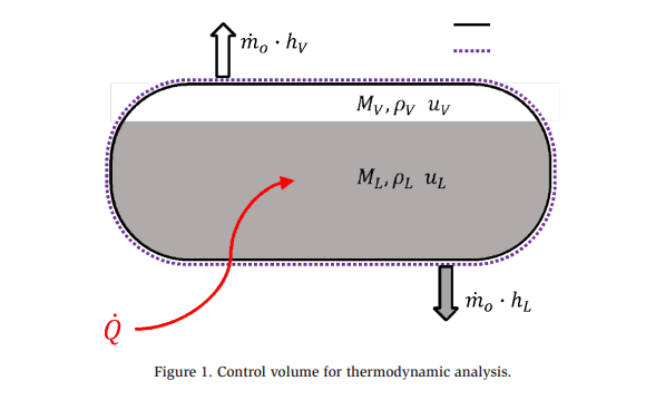
The control volume being considered is illustrated by the dashed line in Figure 1. The resulting mass and energy balances are given below, along with an additional balance in which the overall volume of the vessel is fixed, while the relative volume for the vapor and liquid vary, depending on the location of the relief inlet.

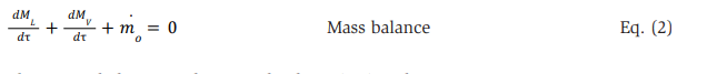
The first term in the mass balance is zero because, in an isolated relief case, there are no mass-flow inlets. Also, the total mass of the control volume is the sum of the mass of the liquid, ML, and the mass of the vapor, MV. The unsteady mass balance then simplifies, as shown in Eq. (2).
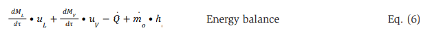
The energy balance on the control volume is given by

Because there is no work associated with the control volume and no inlets, those terms in the energy balance are zero and the energy balance simplifies to
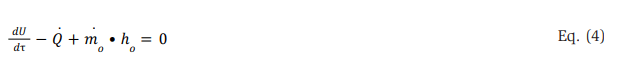
The internal energy of the control volume is given by U=MLuL+MVuV. Taking the derivative of the total control volume internal energy with respect to time, while recognizing the specific internal energy for the liquid and vapor portions of the the specific internal energy for the liquid and vapor portions of the refrigerant in the control varying, the time rate change of the control volume internal energy becomes

The energy balance then becomes
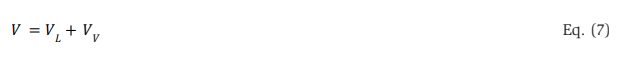
The total control volume, V, is constant, and only the proportion of vapor, VV, and liquid volume, VL, change during the time the relief valve is actuated. The overall volume constraint thus becomes
By differentiating the total volume with respect to time, recognizing the vapor and liquid volumes are related to the fluid density by ![]()
 and that the respective density for the liquid and vapor is invariant during the release so only the mass quantity is changing, the volume constraint becomes
The mass balance [Eq. (2)], energy balance (Eq. 6), and volume constraint (Eq. 8), provide a system of three differential equations that can be simultaneously solved to determine the required mass-flow rate of refrigerant exiting the vessel, , m0 during the relieving condition in order to maintain a constant pressure within the vessel during the relief event for a given state of refrigerant exiting (i.e., vapor or liquid), enthalpy of the fluid leaving, heat load and corresponding state fluid properties within the vessel.
As noted above and indicated in Figure 1, there are two (2) possible inlet conditions for a relief valve. In this case, the inlet condition refers to the phase or state of the refrigerant mass as it is being removed from the vessel––#V for vapor and #L for liquid. Regardless of the phase of the refrigerant mass being removed, the total volume of the component remains unchanged while the relative volumes of the vapor and liquid phases change during the relief event, with the pressure and internal energy of the liquid and vapor being assumed equal and at the saturation conditions. Therefore, the thermodynamic properties (internal energy and enthalpy) of the liquid and vapor phases in the vessel are constant during the release event.
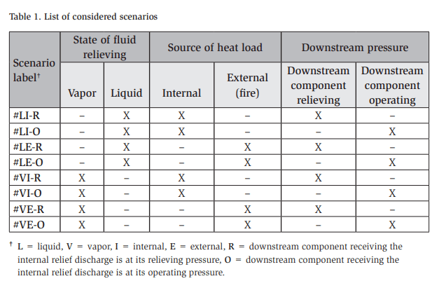
Two other considerations are relevant in the pursuit of engineering a safety relief system for internal relief: (1) the source(s) of heat gain driving the overpressure; and (2) the coincidence of the downstream component receiving the refrigerant being discharged internally. Section §15.3.8.2 of IIAR 2 requires both external and internal heat sources be considered when sizing the relief device. In addition, Section §15.4.6 of IIAR 2 prohibits discharging liquid ammonia into a vent system that discharges directly to the atmosphere. Finally, the analysis of the pressure-relief valves configured to discharge internally needs to evaluate the valve’s operation when discharging to the highest expected downstream pressure (i.e., the downstream component is at its relieving condition) and the lowest expected pressure (i.e., the downstream component is at its normal operating pressure). Table 1 summarizes the various permutations of pressure-relief configurations that include the state of the refrigerant being discharged, the source of the heat creating the overpressure, and the discharge pressure on the relief valve. Each of the listed permutations is identified by a label; these are referred to below as part of our exemplar analyses. For those cases referring to the source of the heat load as “external (fire),” a heat load of 150 Btu/ min-ft2 of projected area of the protected component is assumed. This heat load is consistent with the provisions of IIAR 2, which originated from ASHRAE 15.
Required Relieving Mass Flow of Refrigerant for an Oil-Cooling Heat Exchanger
To illustrate the analysis, consider an ASME-stamped shell-and-tube thermosiphon oil–cooling heat exchanger where the ammonia in the heat exchanger receives 325 MBH (kBtu/hr) of heat internally from the oil. The MAWP of the refrigerant side of the heat exchanger is 400 psig and the heat exchanger measures 8-5/8″ outside diameter and 99-7/16″ in overall length.
For scenario #VI, we assume the oil cooler contains saturated liquid and vapor ammonia at the relieving pressure of 440 psig, which is 110% of the MAWP, and a corresponding saturation temperature of 153.7°F, saturated as it absorbs the heat addition of 325 MBH. In addition, we assume the refrigerant state leaving is vapor
(i.e., mo=mV and ho=hV) for the mass and energy balances. The resulting required mass-flow rate of saturated vapor ammonia leaving the component to maintain the heat exchanger’s pressure at the relieving condition of 440 psig is calculated to be 12.6 lbm/min or a volumetric flow rate of 8.12 ft3 /min of ammonia.
How does this result compare with the calculations required by IIAR 2-2021?
In Chapter 15 of IIAR 2-2021, the applied relief capacity for an internal heat addition conservatively assumes that the required mass-flow rate of the vapor phase ammonia leaving the component is the internal heat addition divided by the heat of vaporization evaluated at the relieving pressure. For the 325 MBH heat addition case, the corresponding ammonia vapor mass-flow rate required to accommodate an external heat addition due to a fire condition is 13.2 lbm/min. This value is slightly higher than that calculated from IIAR 2 because it presumes that all the vaporized liquid leaves the component immediately. A more detailed analysis captures that, as the liquid level drops due to the vaporization, the vapor volume in the component increases, and thus a portion of the vaporized liquid remains resident in the vessel in that newly formed vapor space, rather than leaving through the relief valve.
For Scenario #LI, the same heat addition of 325 MBH is applied, but the mass that is leaving the component is assumed to be liquid (i.e., mo=mL and ho=hL). The resulting mass-flow rate of saturated liquid ammonia leaving the component to maintain the component at its relieving pressure increases substantially to 269 lbm/ min, which corresponds to 60.7 gpm or 8.12 ft3 /min of ammonia. Note, the volume flow rate in this case is identical to that of the vapor case. The equal volumetric flow for both cases is the result of the volume of the pressure-protected component being constant. Therefore, the same volume amount of refrigerant has to be removed, regardless of whether the exiting state is vapor or liquid.
Scenarios #VE and #LE correspond to an external heat addition from a fire. The heat load on the projected area of the heat exchanger is 893 Btu/min. For Scenario #VE, where refrigerant is being relieved from the heat exchanger in a vapor phase, the required capacity is 2.1 lbm/min or 1.34 ft3 /min, where both are on an ammonia flow-rate basis. Section 15.3.8.2.1 of IIAR 2-2021 establishes the relief requirement for pressure vessels based on an external heat load as
![]()
where C is the discharge capacity required of the relief valve (lbm/min of air), D is the overall diameter of the vessel (ft), and L is the overall length of the vessel (ft). The capacity factor, f, for ammonia is 0.5 when combustible materials are not within 20 ft of the vessel. This value for the capacity factor originated from Table 9.7.5 in ASHRE 15-2016, as provided below in Figure 2. Although the conditions for its determination are not specified in ASHRAE 15, it is based on a design pressure of 300 psig and rounded to one significant digit.
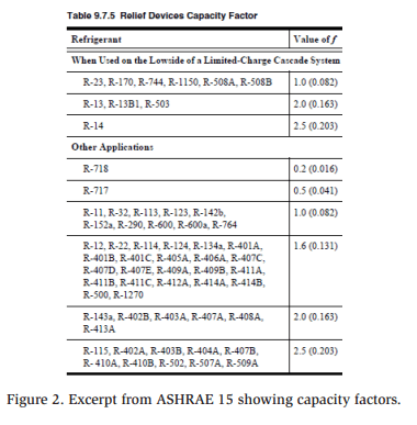
With the proliferation of new fluorochemical refrigerants transitioning into the market, and the wider range of design pressures, ASHRAE has revised its capacity factors. The capacity factors listed in Standard 15 are now refrigerant-specific (as opposed to grouping several refrigerants into one singular value) and vary as a function of the design pressure. By making the capacity factor a function of the design pressure, the capacity factor for a given refrigerant now increases as the design pressure increases. This behavior is a consequence of the decreasing heat of vaporization as the design/relieving pressure increases. Also, Eq. (9) accounts for the conversion of the refrigerant vapor mass flow to an air-equivalent basis in order to facilitate relief-valve selection since vapor service relief valves are certified on an air basis.
Applying Eq. (9), the relief capacity required for an external heat addition to the oil-cooling heat exchanger, with no combustible materials within 20 ft of the heat exchanger, results in a relief-valve capacity of 2.98 lbm/min (air basis) to maintain the pressure of the refrigerant-side heat exchanger at the relieving pressure of 440 psig. The vapor-relief value from the thermodynamic analysis presented above was 2.1 lbm/min (anhydrous ammonia basis). Converting this mass-flow rate from the ammonia rate to an air basis for a refrigerant vapor saturation temperature of 153.7°F, corresponding to the relieving pressure results in a ratio of heat capacities of k=1.77, results in a refrigerant constant of Crefrigerant=385, while the conversion from an ammonia to an air factor of rw=1.311 yields an air-basis mass-flow rate of 2.72 lbm/min, which is slightly lower than the 2.98 lbm/min from IIAR 2. As before, this is lower because of the simplification that assumes all the vaporized liquid is leaving the component. These comparative calculations demonstrate the consistency and agreement of the system of coupled mass, energy, and volume balances presented above, as applied to the refrigerant-containing control volume of an ASME-protected component.
For Scenario #LE, where refrigerant is being relieved from the heat exchanger in a liquid phase, the required capacity is 44.4 lbm/min of ammonia or 10 gpm (which is 1.34 ft3 /min). Because the internal heat load results in a larger capacity, that case becomes controlling for the purposes of relief-valve selection.
In Appendix G of IIAR 2-2021, the liquid relief capacity applied for a given heat load condition only considers the volumetric expansion of trapped liquid with no vapor space. In addition, the resultant value is given in gpm (water) to facilitate the selection of a liquid service relief valve. For the 325 MBH heat addition, and the volumetric expansion of ammonia given as 0.00164 °F-1 in Appendix G, the relief capacity required is only 1.55 gpm (water). By comparison, the liquid volumetric flow rate required to maintain the pressure in a component only partially filled with a volatile liquid refrigerant is much higher. This should not be surprising because the volume expansion caused by a temperature change in non-vaporized (e.g., subcooled) liquid ammonia is small. However, the specific volume (i.e., density) difference between the liquid and the vapor is quite large, particularly for anhydrous ammonia. At a relieving pressure of 440 psig, the volume of the liquid increases by more than 21 times as it evaporates to a vapor state. The small volume expansion in liquid ammonia is the reason that the industry’s conventional wisdom on liquidrated relief valves is that they are much larger than needed. However, while this is true for the volumetric expansion of a component completely full of a non-volatile liquid (e.g., oil or the hydrostatic protection of pumped liquid piping), it is not true in the case of relieving a liquid out of a partially volatile liquid–filled component inside which vaporization of the liquid is occurring. The equation in Appendix G is for the liquid-rated relief of a non-volatile fluid due to volumetric expansion only.
Impact of Back Pressure on Internal Relief Valve Performance
Because the pressure ratio across the relief valve is higher for internal relief than for atmospheric relief, the capacity of the relief valve will be affected. The manufacturers of the most commonly used pressure-relief valves in the industrial refrigeration industry do not provide a methodology for adjusting the capacity when configured for the increased inlet and outlet pressures expected for internal relief arrangements There are methodologies for this adjustment in kindred industries that have not been adapted for the refrigeration industry.
VAPOR RELIEF
An issue that arises with internal relief is the evaluation of the impact of the significantly higher inlet pressures and back pressures inherent in internal relief arrangements on the capacity and stability of relief-valve operation. For a vaporrated relief valve, an estimate of the reduction in capacity for pilot-operated relief valves over a range of back pressures can be calculated using Table T7-1 from Crosby (1997), as shown in Figure 3.
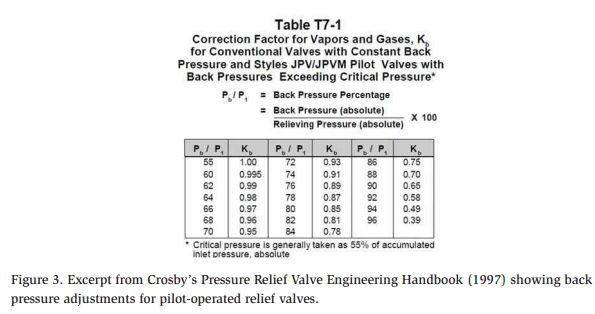
The adjustment factor shown in the figure, Kb, is used as follows:

where Cact is the actual capacity of the relief valve and CR is the rated capacity of the relief valve. Both capacity values are on the certified basis.
Emerson’s Pressure Relief Engineering Handbook (2012) has correction factors for conventional, balanced, and pilot-operated relief valves. The base equation for the correction factor is as follows:
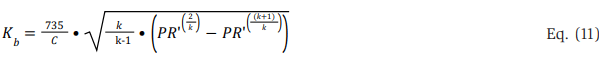
where C is given by

where k is the ratio of specific heats (k = 1.4 for air) and PR’ is an adjusted pressure ratio for each relief-valve model in the following form:

where a and b are constants model-specific to the relief valve, Pb is the downstream absolute pressure, and P1 is the upstream absolute pressure.
Since we do not have coefficients a and b for the conventional relief valves commonly applied in our industry, a first approximation would be to use a PR’ value equal to the pressure ratio. Note that this reasonably approximates the value in Table T7-1 from Crosby, shown in Figure 3. However, the adjustment used for all of the conventional relief valves in the Emerson publication results in a lower Kb (i.e., less capacity) as a function of the pressure ratio based on that assumption. The worstcase capacity reduction used to adjust the pressure ratio can be approximated with a=0.6 and b=0.4. Therefore, to be conservative, we applied these factors to adjust the capacity with the back pressure. When determining the pressure ratio, there are two conditions that should be considered: (1) when the downstream component is at its relieving condition (smallest pressure ratio); and (2) when the downstream component is at its lowest and highest operating pressures (highest pressure ratio). Table 2 gives the adjustment factor, Kb, for the pressure ratios that would commonly be expected in our industry.
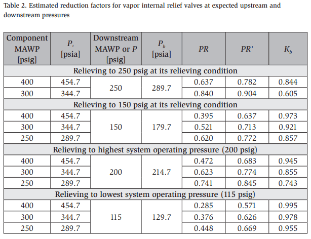
For Scenario #VI-R, with a 440 psig relieving (i.e., upstream, P¹ ) pressure discharging vapor to a 275 psig (relieving [R] pressure assuming no built-up back pressure) downstream pressure (Pb), the absolute pressure ratio ( ![]() is 0.637 (assuming a sea-level atmospheric pressure of 14.7 psia), resulting in a Kb of 0.844, as indicated in Table 2. Note that Kb is the ratio of the capacity of the relief valve at the relieving pressure, not at the relief valve’s stamped set pressure (i.e., pressure differential). In this particular case, the relief valve set pressure is 150 psig so as to accommodate the differential pressure between the component’s MAWP and the downstream component’s MAWP. Therefore, the capacity that is being adjusted is the relief valve’s rated capacity at a 400-psig set pressure.
is 0.637 (assuming a sea-level atmospheric pressure of 14.7 psia), resulting in a Kb of 0.844, as indicated in Table 2. Note that Kb is the ratio of the capacity of the relief valve at the relieving pressure, not at the relief valve’s stamped set pressure (i.e., pressure differential). In this particular case, the relief valve set pressure is 150 psig so as to accommodate the differential pressure between the component’s MAWP and the downstream component’s MAWP. Therefore, the capacity that is being adjusted is the relief valve’s rated capacity at a 400-psig set pressure.
This raises an important point when specifying an internal relief valve. That is, the selected relief valve needs its certified capacity pressure range to correspond with the upstream pressure for which the relief valve will actuate. In addition, it is important to ensure that the body of the relief valve is designed for the pressures it will experience on both its inlet and outlet sides.
Once again, the conversion from the ammonia flow rate to an air basis is estimated at the saturated relieving temperature of 153.7°F, a k=1.77, corresponding to a Crefrigerant=385, and an rw=1.311. Therefore, the capacity calculated for Scenario #VI, with its required 13.2 lbm/min mass-flow rate of ammonia vapor, would require a relief valve with a capacity of 17.3 lbm/min on an air-equivalent basis. Using the reduced capacity adjustment factor of Kb=0.844,, the relief-valve rated capacity required is 20.5 lbm/min of air. For this internal relief case, the capacity (i.e., vapor flow rate) of the internal relief valve is “passed on” to the downstream component, and its relief valve capacity must be upsized to accommodate the additional flow expected from the internal relief.
Is it reasonable for the downstream conditions of Scenario #VI to assume an internal heat addition of 325 MBH to be applicable at the downstream component’s MAWP plus the allowed overpressure?
That would mean the scenario is starting the compressor with the oil cooler isolated during an overpressure event on the high side of the refrigeration system––a scenario that seems unlikely. The applicable scenario in this case would more likely be the fire condition––Scenario #VE-R. In this case, the oil cooler requires a relief valve with a capacity of 2.98 lbm/min of air to maintain the pressure at 440 psig based on fDL in IIAR 2-2021 for the component (8-5/8″ D x 99-7/16″ L), with no combustible materials within 20 ft. The relief valve’s capacity needs to be adjusted to accommodate a de-rate of 0.844, which would result in a relief valve with a required capacity of 3.53 lbm/min of air when configured for internal relief. S
cenario #VI-O is identical in all aspects except that, should the vapor be relieved during operation (O), the downstream pressure would be in a pressure range of 115–200 psig. Note that a 150-psig set pressure internal relief valve will lift at a lower upstream pressure and will have a lower capacity at that reduced relieving pressure. However, because that pressure is lower than the MAWP of the component if it does not have the capacity at those conditions, the pressure in the protected component is allowed to rise until it reaches the MAWP plus its allowed overpressure. At these conditions, the adjusted capacity of the relief valve is the same as in Scenario #VI-R, but with a higher capacity adjustment factor of Kb=0.945. At the highest expected system operating pressure of 200 psig, the required relief-valve rated capacity would be adjusted to 18.3 lbm/min of air.
Note that there is a significant effect on the capacity adjustment factor with a lower set pressure-relief valve (e.g., 50 psi). Had the example oil cooler had an MAWP of 300 psig discharging to 250 psig, the adjustment would be larger. Assuming 330 psig upstream and 275 psig downstream, the two pressures in absolute pressure units is 0.84 (assuming a sea-level atmospheric pressure of 14.7 psia), which results in a Kb of 0.605, as shown in Table 2.
This comparative analysis shows that the required relief-valve capacity is set by the internal heat addition during a maintenance scenario at the highest operating downstream pressure. The added capacity of the relief valve protecting the downstream component becomes the sum of the capacity required for the fire condition on non-isolated oil coolers plus the capacity of the relief valves for the isolated oil coolers during the fire scenario.
LIQUID RELIEF
For Scenario #LI-R, a relief valve rated at 100 psi differential pressure is applied to pressure protect a 300-psig MAWP vessel discharging to a 275-psig downstream pressure. The protected vessel requires a liquid volume flow rate of ammonia of 67.95 gpm. At the relieving condition, the upstream relieving pressure is expected to the upstream relieving pressure is expected to be 385 psig, which includes the additional 10% psi pressure difference across the relief valve at the relieving condition, the CV of the condition, the of the relief valve needs to be 4.676 gpm/psi0.5

The relief valve is sized with consideration for its set pressure difference (in this case, 100 psi plus the allowed 10% overpressure), and the flow coefficient value for the relief valve should be adjusted for the effects of liquid flashing as it flows through the relief valve, although this is not the case in this analysis. The effects of flashing flow necessitate an increase in the required CV of the relief valve (i.e., a larger relief valve). However, this adjustment is not included here for the sake of brevity. Translating the liquid flow rate into a water basis, the rating of the valve needs to be 50 gpm at the 100-psig set pressure.
When a liquid relief device actuates, liquid refrigerant flows from the higher upstream pressure to the downstream pressure, where a mixture of liquid and flash gas leaves the valve’s outlet, and into the downstream “vent piping.” In this particular example, the flash vapor component is 19.3 lbm/min of ammonia, with the balance of the discharging mass flowing in a liquid state and with both components in equilibrium at the saturation temperature corresponding to the downstream pressure. The downstream vessel receiving the relieving refrigerant vapor will need to have its required relief capacity increased for the additional vapor mass-flow rate from the internal relief valve, as well as any other internally receiving component expected to coincidentally discharge. The conversion from the ammonia flow rate to an air basis for the flash vapor is estimated at the saturated downstream temperature of 120.8°F, a k=1.60 corresponding to a Crefrigerant=372.5, and an rw=1.318. For the above-sized relief valve, the capacity of the relief valve on the downstream component would need to increase by 25.44 lbm/min of air to accommodate the discharging vapor flow rate from the internally relieving liquid service relief valve. IIAR 2-2021 Appendix G states that the capacity does not have to be “passed on” for liquid relief, but this is only the case for the pressure relief of non-volatile liquids. It is not the case when discharging a volatile refrigerant internally.
Once again, it is not reasonable for Scenario #LI-R, corresponding to an internal heat addition of 325 MBH, to be the basis for determining the added relief capacity load imposed on a downstream component. For Scenario #LE-R, the external heat (i.e., fire) condition is 53.6 MBH (150 Btu/min-ft2 ), and this would require the relief of 11.2 gpm of ammonia to maintain the pressure difference of 110 psi (385-psig relieving pressure). For that same pressure difference of 110 psi, and accounting for the flashing flow, the CV of the relief valve would need to be 0.786 gpm/psi0.5. Translating that into water, the rating of the valve would need to be 8.25 gpm at 100 psi. The effect of the liquid refrigerant expanding to the downstream pressure, forming flash gas, results in 3.18 lbm/min of ammonia vapor (4.19 lbm/min of air). However, as mentioned above, the flow passed on to the downstream relief valve is determined by the capacity of the relief valve, not the heat addition.
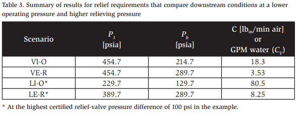
For Scenario #LI-O, a 100-psi differential pressure is discharging to a 115-psig downstream pressure, requiring a volume flow rate of ammonia of 106 gpm. For that pressure difference (110 psi), and accounting for the flashing flow, the CV of the relief valve would need to be 7.67 gpm/psi0.5 or 80.5 gpm at 100 psig on a water-equivalent basis. The downstream flash vapor in this case would be 43.9 lbm/min of ammonia (57.86 lbm/min of air). However, this technically does not need to be passed on to the sizing of the relief valve on the downstream component because that component is operating and its relief device is not relieving (i.e., the system is operational) under this scenario. However, because the relief-valve capacity required is larger than the requirement for Scenario #LE-R, the flash vapor based on the relief-valve’s capacity would need to be added to the downstream component’s relief capacity if the relief scenario includes an isolated oil cooler (i.e., a fire scenario with an oil cooler isolated for maintenance). Table 3 summarizes the results from these various cases.
The analysis presented in this section assumes the use of a liquid-rated relief valve with a set pressure of 100 psig. The reason a larger pressure difference was not used is that the liquid-rated relief valves supplied by the manufacturers in our industry are typically certified in a set pressure range of 50–125 psig.
How do these valves behave at higher pressure differences?
While some liquid relief valve manufacturers provide a single CV that is applicable over a range of certified pressures (e.g., 50–100 psi), other manufacturers have their valves certified at only a single set pressure value. In other words, a single model of relief valve has three (3) separate certifications––one each for 50-, 75-, and 100- psig set pressures. This raises a question as to whether all the valves will have a single CV applicable at differential pressures greater than (or outside the range of) the certification. If the designer is unsure, sizing the relief devices should be based on the rated pressure differential, as was done in this example.
Should we allow the relief valve to go from the 440-psig discharging to 115 psig in Scenario #LE-O?
While that would make the relief valve capacity smaller, the operation of a relief valve outside of its certified range would call the capacity into question when trying to show compliance and so should not be done.
Practically speaking, it is unclear how certified liquid-rated relief valves will work with either a volatile fluid (flashing through the valve) or at higher differential pressures.
What is the capacity at an elevated upstream pressure?
What is the effect of the flashing of liquid to vapor as it expands to the lower downstream pressure? In our opinion, this should limit the application of liquid-rated relief valves to non-volatile fluids only (e.g., oil) because the questions above indicate that the designer is not allowed to show compliance when using liquid-rated relief valves with a volatile fluid (e.g., refrigerant). The good news is that internal relief should almost exclusively be done with vapor-rated relief valves, based on the information presented in this paper.
Internal Relief Vent Piping Requirements
The maximum allowable relief-valve back pressure, and the methodology for its calculation when discharging to an atmospheric vent piping system, is outlined in detail in IIAR 2-2021. However, despite the requirement for pressure-drop calculations for both atmospheric and internal relief, there is no specificity with respect to either the allowable built-up back pressure or the methodology for calculating the internal relief vent piping pressure drop.
For the internal relief of vapor, a possible pressure-drop calculation methodology would be to use the same approach as for atmospheric relief, with the pressure being a known downstream pressure. The known downstream pressure would be the set (or relieving) pressure for the downstream component receiving the internally discharged vapor. The analysis would be done on air, the analysis systematically applied until the refrigerant reaches the larger downstream system piping or component. The maximum allowable back pressure, presumably, would be the same as for atmospheric relief, and an allowed back pressure of 10% of the set pressure seems to be a reasonable start. Note that this viewpoint needs to be validated before initiating a change to the IIAR 2 standard in the future.
For liquid relief, the situation of determining the back pressure from a relief event gets much more complicated due to the likely presence of two-phase flow in the downstream piping, as well as the effects of elevation changes (i.e., a vertical rise) in the downstream piping. Couple that with the challenges associated with properly siting the inlet for a liquid-rated relief valve below the liquid level and the determination of the capacity at pressure differences outside of the certified range of pressure differences. This leads us to not recommend the application of the internal relief of volatile liquids. Because it is not recommended, no consideration as to how to determine the pressure loss is offered. The analysis in IIAR 2-2021 Appendix G is appropriate for the relief of a non-volatile fluid (e.g., oil).
Conclusions
The thermodynamic analysis of a partially filled liquid-containing component confirms the vapor-relief flow-rate requirements in IIAR 2 and its predecessors and extends the analysis to liquid relief flow rates. The flow rates required for relieving volatile liquids are much higher than the requirements given in IIAR 2-2021 Appendix G. In addition, the complication of calculating the pressure drop in the downstream piping means we do not recommend application of the internal relief of volatile liquids. Rather, we recommend limiting the application of internal relief to only vapor-rated relief valves and liquid service relief valves applied to non-volatile liquids.
A relief valve with the differential pressure required to maintain the component at its MAWP can be specified but should be certified up to the component’s MAWP. For example, a component with a 400-psig MAWP discharging internally to the high side, rated at 250 psig, would require a 150-psig differential (i.e., set) pressure. The chosen relief valve should be certified up to 400 psig so that the relief-valve capacity can be determined at the relieving pressure.
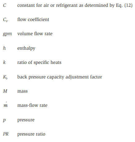
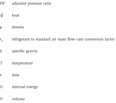
Nomenclature
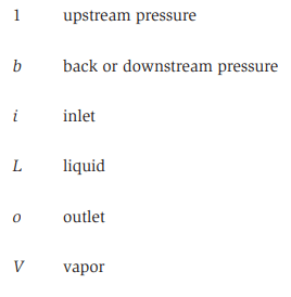
Subscripts
References
ASME, ASME Boiler and Pressure Vessel Code Sections VIII and XIII, 2021.
Crosby Valve Inc., Crosby Pressure Relief Engineering Handbook, Technical Document TP-V300, 1997.
Emerson, Pressure Relief Engineering Handbook, Technical Publication TP-300, 2012.
EPA, “Risk Management Program” rule, U.S. Evironmental Protection Agency, 40 CFR Part 68.
IIAR, ANSI/IIAR 2 Standard for Design of Safe Closed-Circuit Ammonia Refrigeration Systems, 2021.
OSHA, “Process Safety Management for Highly Hazardous Chemicals,” U.S. Occupational Safety and Health Adminstration, 29 CFR 1910.119.
Reindl, D.T., T.B. Jekel, Scenarios for Engineering Headered Safety Relief Vent Systems, 26th International Congress of Refrigeration, pp. 1983–1990, 2023.
Acknowledgments
We are grateful for the input we received from the IIAR Standards Committee members and for the support of the Industrial Refrigeration Consortium and its member companies.