
2024 Technical Paper RR 1 – Research Report
Correlation Between Evaporator Suction Pipe Size and Hot Gas Flow Rate for the Prevention of Hydraulic Shock in Ammonia Refrigeration Systems
Chidambaram Narayanan, External Consultant
Joel-Steven Singh, Senior Engineer
AFRY Switzerland AG
Executive Summary
Incidents of ammonia releases due to hydraulic shock in the refrigeration pipework have been reported in the past and, unless preventive steps are taken, could occur in the future. Such shock events carry significant commercial risks and is a concern for health and safety of humans. Two locations where hydraulic shock occurs most frequently are, (a) in the evaporator coil headers at the beginning of a hot gas defrost sequence, and (b) in the wet suction piping from the evaporator at the end of the hot gas defrost sequence. These are the times when the operating pressure in the coils is being changed from refrigeration to defrost and from defrost back to refrigeration. Research on characterizing hydraulic shocks in ammonia systems was conducted through two impactful projects funded by ASHRAE. The first one being RP-970 (Martin, Brown, & Brown, 2007) where detailed experiments resulting in a database of hydraulic shock amplitudes for various operating conditions such as gas flow rate, , gas to liquid ratio and operating temperatures were carried out. This was followed up by RP-1569 (Narayanan, Thomas, & Lakehal, 2020) wherein a verified and validated CFD model was developed using the experimental data as a basis. Application of this CFD model to a real incident (Narayanan, Wiencke, & Loyko, 2021) involving pipework failure, which predicted a shock amplitude upwards of 4000 psia; in agreement with the metallurgical analysis for the kind of rupture of the pipework observed in this incident.
This was followed by a project funded by ARF (Narayanan C. , 2022) that consisted of a comprehensive parametric study involving 150+ three-dimensional unsteady simulations using High Performance Computing systems. The study focused on a piping configuration of horizontal pipes initially filled with saturated ammonia liquid to 50% of their diameters. A correlation developed in that study could be used to calculate the shock potential of piping configurations similar to those studied in the project. The critical mass flow rate for slug formation, a prerequisite for downstream hydraulic shock, was also developed. The study also defined the opening times for motorized valves that could prevent or dramatically reduce the potential shock pressures.
The above correlation developed for fast-acting valves, however, underestimated the shock potential to the accident scenario analyzed by Wiencke (2008). This pointed to the fact that the correlation derived, based on a scenario with an initial layer of stagnant liquid in the pipe, would systematically underpredict shocks for the accident scenario where there was no initial liquid, and the liquid slug was formed in a trap before it entered the pipe. When there is a layer of stagnant liquid all along the pipe the slug velocity would be lower since as the slug moves it comes into contact with a stagnant layer of liquid in front of it. Based on the above observation, it is apparent that the strongest shock pressures would be achieved in nominally dry pipes.
Therefore, the current study focused on quantifying the possibility and magnitude of a hydraulic shock during the hot gas defrost of industrial ammonia refrigeration systems. The scenario considered the presence of a pre-formed slug that is driven into the pipework leading to the evaporation coil by the hot-gas flow. In contrast, earlier studies considered the condition where a slug is formed over a high-enough liquid layer due to the lift-up of liquid through the shear acting on the liquid surface by the hot-gas flow over it. The pre-formed slug scenario is considered a more severe condition due to a higher shock potential. The hot-gas mass flow rate required for the gas shear to scoop up liquid and form a slug is higher than the critical mass flow rate required to transport a pre-formed slug through the pipework. Additionally, the shear-induced slug achieves a lower speed as it travels over a thick stagnant liquid layer as compared to a pre-formed slug that moves over a thin liquid layer.
Through a careful preliminary study to determine the pipework length and pre-formed slug length, the pipework length used for the parametric study conducted was 100D along with a slug length of 10D. In
this study, it was also found that a pre-formed slug in a dry pipe does not have sufficient condensation potential and will not form a hydraulic shock for long-enough pipes (> 50D). Therefore, all simulations were performed with a thin liquid layer of 0.2D height in the test section. A phenomenological model based on a densimetric Froude number was used to propose an estimate of a critical mass flow rate below which a pre-formed slug would collapse under the influence of gravity and not result in a hydraulic shock. The parametric study considered diameters from 1” to 16”, three evaporation temperatures of -45°F, -30°F, and -20°F and mass flow rates going from 1/6th to 16 times the critical mass flow rate of slug transportation.
Using the results of the parametric study, in particular the slug Joukowsky number for each case, a linear regression model (and a machine learning model) with high accuracy and correlation to the simulation results was developed. This correlation generated using the 1” to 10” pipe diameter data was successfully validated for the 12” and 16” diameter case. It was also able to successfully predict the accident scenario studied by Wiencke (2008). This correlation can be used to determine the maximum safe size of the hot-gas valve for a given suction pipe diameter and evaporation temperature based on the shock potential for that case.
1. Introduction
Incidents of ammonia releases due to hydraulic shock are still occurring. Under the best-case scenario, a hydraulic shock that causes a mechanical failure results in downtime for a plant. Larger shocks leading to significant ammonia releases can result in health effects to plant personnel, and neighboring communities. Two locations where hydraulic shocks occur most frequently are, (a) in the evaporator coil headers at the beginning of a hot gas defrost sequence, and (b) in the wet suction piping leaving the evaporator at the end of the hot gas defrost sequence.
Over the past 30+ years, several ammonia refrigerant leaks have occurred as a result of a failure of the piping associated with an ammonia evaporator or other low temperature piping. Over the past 20 years, careful analysis of these failures has revealed that large pressure surges generated inside the refrigeration system caused these failures. It was observed that even though the pressure surges were strong enough to break welds, nearby relief valves did not operate to protect the piping. These same relief valves performed adequately when tested after the event. The only explanation for this, that the pressure surges were of extremely short durations, was provided by Martin et al. (2007). It is now known that condensation-induced hydraulic shocks (CIHS) were the most probable cause of these failures. A well-documented failure of an 8” evaporator coil header operating at -50°F in an ammonia system serving a spiral freezer in a frozen food factory is presented by Wiencke (2008).
CIHS occurs when there is accumulated or stratified liquid flowing in the piping, over which or behind which vapor at high velocity is introduced during a pressure transient. For a horizontal pipe partially filled with liquid, there is a shearing force of the gas acting on the gas-liquid interface. The interface forms waves which eventually grow to form slugs covering the complete cross-section of the pipe. Further flow of vapor pushes the slug toward a pipe end closure or a valve. As the trapped vapor gets pressurized, it condenses onto the oncoming slug and on the pipe walls. Thus, the slug does not experience any resistance to its motion and eventually collides with the end closure resulting in a hydraulic shock. As per IIAR guidelines, such a phenomenon can happen at the beginning of hot gas defrost as a result of liquid slugs in the hot gas piping to coils that are mostly filled with liquid or at the termination of defrost as a result of slugs formed in the two-phase suction lines flowing into sections of the piping that are closed and have no exit.
The shock pressures that are generated are commonly much higher than the maximum allowable working pressure of the low side of a refrigeration piping system and/or the setting of the pressure relief safety valves installed and designed to protect the system. It can now be confirmed through CFD modelling (Narayanan, Thomas, & Lakehal, 2020) that these high-peak-pressure, short-duration, hydraulic shock pressure waves can exceed the ultimate strength of common low temperature ammonia refrigeration system piping. In addition, the transient pressure amplitude only exists for a short duration and is very localized. If a pressure relief device would be installed close to the location where the shock event occurs, the short duration of the pressure rise would be too fast for the pressure relief valve to respond.
1.1 Background
Martin et al. (2007) in ASHRAE Research Project RP-970 built a test rig around a 20 ft long, 6-inch Sch. 80 pipe section that was fully instrumented to capture a hydraulic shock event. Slug formation, slug velocity and shock pressure were measured for 292 individual test runs. Mass flow rates were varied so that thresholds for the occurrence of shocks were established at different initial void fractions. For
the first time, an extensive database of hydraulic shock data for anhydrous ammonia was available. To carry this research forward, the ASHRAE project RP-1569 was initiated in 2015 to develop and validate a CFD model based on the experimental data (Narayanan, Thomas, & Lakehal, 2020).
The study resulted in the first successful three-dimensional CFD simulation of the CIHS phenomenon (Narayanan, Thomas, & Lakehal, 2020). The pressure signatures obtained by the simulation are strikingly similar to the experimental results. Slug speeds, shock formation times, and shock amplitudes were predicted with reasonable accuracy for a variety of liquid depths, temperatures, and vapor flow rates. The model confirmed the direct correlation between slug formation in the horizontal test pipe and the creation of a hydraulic shock
This CFD model implemented into TransAT software (AFRY Switzerland, 2020), was then applied to an incident described by Wiencke (2008), wherein the cause for the pipework failure was attributed to a massive hydraulic shock (> 3000 psia) during the hot gas defrost cycle for a postulated condition of the evaporator load. The carefully setup forensic CFD model predicted a hydraulic shock of around 3500 psia for this case (Narayanan, Wiencke, & Loyko, 2021), which was much beyond the experimental range of Martin et al. (2007); thereby, demonstrating the relevance and utility of the CFD model to real industrial systems.
This was followed by a project funded by ARF (Narayanan C. , 2022) that consisted of a comprehensive parametric study involving 150+ three-dimensional unsteady simulations using High Performance Computing systems. The simulation results were analyzed to answer questions on what type of valves (fast acting or motorized) should be employed for hot gas defrost process, sizing of valves, dependence on suction temperature, risk due to trapped liquid, among other important drivers of hydraulic shock risk. The study focused on a piping configuration of horizontal pipes initially filled with saturated ammonia liquid to 50% of their diameters based on the finding that for partially filled pipes the maximum shock levels were obtained for this level of liquid. A correlation was derived giving the dependence of shock pressure on all the parameters such as hot gas mass flow rates, pipe diameter, and pipe length for partially filled pipes. This correlation could be used to calculate the shock potential of piping configurations similar to those studied in the project.
The effect of opening times in motorized valves on the hydraulic shock potential was also studied ( (Narayanan C. , 2022)). The study found that valve opening times greater than the slug travel time (system length divided by the average slug velocity) can dramatically reduce the potential shock pressures. Hydraulic shock amplitudes can be significantly reduced simply by increasing the valve opening times of the hot gas supply valve that opens to initiate hot gas defrost, and the suction stop valve that opens at the termination of a hot gas defrost. The opening time can be estimated using the above-mentioned correlation that gives the slug speed and the piping length.
In spite of the above successes, the shock potential predicted by the correlation was much lower than the simulation results for the accident scenario presented by Wiencke (2008). This points to the fact that the correlation derived, based on a scenario with an initial layer of stagnant liquid in the pipe, would systematically underpredict shocks for the accident scenario where there was a pre-formed slug in the pipework. When there is a layer of stagnant liquid all along the pipe the slug velocity would be lower since as the slug moves it comes into contact with a stagnant layer of liquid in front of it. Based on the above observation, it is apparent that the strongest shock pressures would be achieved in nominally dry pipes. Therefore, this project studies shock pressures resulting from preformed slugs traveling in dry pipes.
1.2 Objectives
The purpose of this study is to provide the shock pressure data and an estimate of the maximum mass flow rate above which the probability of a hydraulic shock during defrost is non-zero. In other words, to link the size of a suction pipe and the mass flow of hot gas so that hot gas valves can be safely sized based on shock pressure thresholds once they are established.
It must be noted that this work does not intend to determine what is, or is not, an acceptable threshold shock pressure for ammonia suction lines but only to express the correlation between hot gas flow rates and potential shock pressures.
1.3 Scope of Work
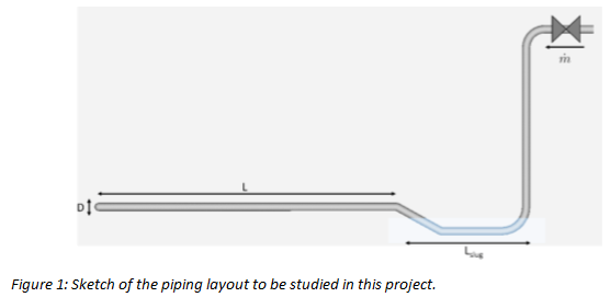
This project is the first systematic CFD investigation into hydraulic shock in nominally dry horizontal pipes in anhydrous ammonia refrigeration systems. The piping layout consists of a test pipe with a saturated liquid-filled trap at the entrance to the test pipe as shown in Figure 1. A surge of 100 Psig ammonia hot gas is introduced on the upstream side of the trap to push the liquid out of the trap and into the test pipe thus creating a moving liquid slug. The study examines a full range of pipe sizes, and lengths, operating at relevant ammonia system suction temperatures. The flow rate was increased in increments to find both the critical mass flow rate below which there is no slug movement, and the rise in the potential shock pressures associated with the hot gas flow rates. It is proposed to perform simulations for 1”, 2”, 4”, 6”, 10”, 12” and 16” pipes and for three ammonia suction temperatures of -45°F, -30°F and -20°F.
For the various geometrical mesh setups, a gas flow would be initiated at the inlet to the downcomer pipe pushing the liquid in the trap into the horizontal section of pipe as a slug and was run until the slug impacted the end closure. The average velocity of the slug at various points along the run of horizontal pipe was stored for each simulation.
2 Methodology
The emphasis of this research is to evaluate generic piping designs in the hot gas piping between the valve group and the evaporator header where hydraulic shock occurs most frequently. The following quantities are considered as variable parameters,
- Hot gas mass flow rate,
- Pipe diameter,
- Evaporating temperature, and
- Pipework length.
The maximum pipe length and pre-formed slug length were determined in a first phase and used for the remaining part of the study. Considering the pipe length as a parameter would require an order of magnitude larger number of simulations – making the study impractical both in terms of time and resources. Instead, a preliminary study was undertaken to study the effect of the pipework length and arrive at an optimal length to diameter ratio which could be used for the parametric study. The slug length represents a scenario where significant amount of liquid is trapped in the system and is chosen as a conservative parameter; practically, it would be difficult for a designer to estimate this quantity. This aspect was analyzed in the second preliminary study.
2.1 Mathematical Modelling
The mathematical model used in this study is the compressible non-equilibrium multiphase mixture model as presented in Labois and Narayanan (2017) as implemented in the TransAT© software which is a finite-volume CFD solver specialized in the modelling of multiphase flows. The TransAT CFD software was further developed to handle the problem of hydraulic shocks during the ASHRAE RP-1569 project and validated with the experimental data of RP-970 (Narayanan, Thomas, & Lakehal, 2020).
Turbulence is modelled using the mixture Reynolds averaged Navier-Stokes (RANS) approach. The conservation equations of mass are solved for each phase, whereas the momentum, pressure, and temperature are solved only for the mixture.
The process of creation of a hydraulic shock depends on the propulsion of the liquid slug due to condensation of the trapped gas pocket downstream of the slug leading to its eventual collapse. Therefore, sufficiently accurate modelling of condensation is necessary to predict the formation of a hydraulic shock. Condensation can occur via different mechanisms or modes, such as interfacial condensation, dispersed-phase condensation, wall condensation and due sudden rise in pressure. The liquid and gas densities and other properties such as the latent heat of condensation, the saturation curve, etc. have been compared with data available in the NIST Database for Ammonia (Narayanan et al. (2020)).
2.2 Problem Setup
The geometry and setup are shown in Figure 1. The flow problem is governed by geometrical parameters given by, the pipe diameter (D), the length of the horizontal part of the pipe (L), radius of the elbow (RL), and the length of the liquid trap which holds the pre-formed slug. The parameters controlling the flow are the evaporation pressure and temperature (pe, Te), the inlet hot-gas mass flow rate (Min), and the pipework diameter.
3 Parametric study
The following parameters were considered in the parametric study, where parameters such as elbow radius and acceleration due to gravity are already fixed.

Based on the preliminary analysis, the length to diameter ratio of the test section was set to L/D = 100, and the length of the pre-formed slug was set to 10D. The simulations for L/D = 100 also provide the potential hydraulic shock amplitude for L/D 10-100 based on the intermediate slug speed data from the simulations.
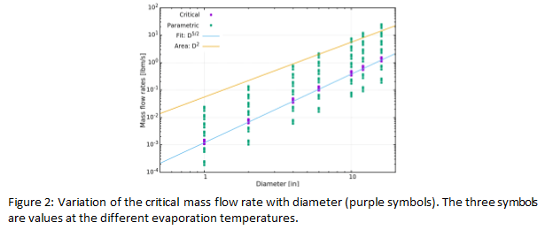
The simulated parameters are shown in Table 1. The six different hot-gas mass flow rates were chosen relative to the critical mass flow rate of slug transport. The choice of the mass flow rates should be such that the critical mass flow rate below which no shock occurs could be determined. A simple non-dimensional analysis was performed to estimate the critical mass flow rate based on the ratio between the driving force, i.e., the hot-gas momentum and the gravitational head of the slug. This ratio is referred to as the densimetric Froude number. It was postulated that for values of the Froude number much less than one, there would be a collapse of the slug to the bottom of the pipe, whereas for higher values the slug could move as a unit to eventually form a hydraulic shock.
The critical mass flow rate is given as,
Where the critical Froude number is set to Fr𝑑crit=0.01. The variation of the critical mass flow rate (purple points for the three different evaporation temperature) as a function of the pipework diameter is presented in Figure 2. The figure also shows the mass flow rates that were used for the simulations as multiples of the critical mass flow rate (1/6, ½, 2, 4, 8, 16 times). The critical mass flow rate reduces rapidly with diameter, for example from slightly above 1 lbm/s at a diameter of 16” to approximately 0.001 lbm/s for a 1” pipe. Based on such a choice of the mass flow rates, we expect no shock to occur for the first two mass flow rates and detectable shocks for the higher four mass flow rates.
3.1 Slug Joukowsky Number
The Joukowsky number of a liquid slug, used as a decisive parameter to estimate the shock potential of a certain suction pipework, is defined as follows.
![]()
where 𝜌𝑙 is the liquid density, 𝑐𝑙 is the speed of sound in the liquid, and 𝑣slug is the velocity of the liquid slug. The Joukowsky number has the dimension of pressure and is a number widely used to estimate the pressure surge caused when a fluid in motion is forced to stop or change direction suddenly, such as due to a sudden valve closure. The slug Joukowsky number was shown to be a reliable and accurate predictor of the hydraulic shock amplitude and is the main output of the simulations.
3.2 Simulation Results
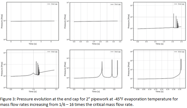
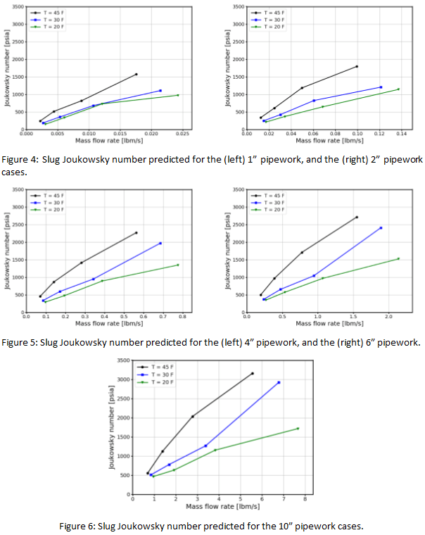
For all three evaporation temperatures, no shock was observed for mass flow rates below the critical mass flow rate (1/2 and 1/6th) and a clear shock was observed for all cases above the critical mass flow rate. This verifies the phenomenological understanding used to derive the critical mass flow rate estimate. The pressure variation at the end cap for the set of 2” pipework cases at -45°F is shown in Figure 3. It is clearly observed that the cases with mass flow rate below the critical mass flow rate do not produce a shock even after a long time (3.5 – 4 seconds), whereas the case with the highest mass flow rate produces a strong shock at around 0.36 seconds. This behavior was observed for all other diameters and evaporation temperatures. The complete slug Joukowsky numbers for 1”—10” diameters are presented from Figure 4 to Figure 6. The pattern is similar in all cases, except the increase in the slug Joukowsky numbers. This is due to the fact that as the diameter increases, the critical mass flow rate increases at a faster rate than the increase in the cross-sectional area of the pipe (as shown in Figure 2). This means that we are simulating higher bulk velocity cases as the diameter is increased.
3.3 Slug Joukowsky Number Variation Along the Pipework
The simulations for a pipework length of 100D can also be used to provide the shock or slug Joukowsky number estimates at distances from 10D-90D. The variation of the slug Joukowsky number along the pipework, normalized by the final slug Joukowsky number was studied. It was observed, that at the
owest temperature the slug speed gets established early on and remains constant. At higher temperatures, slug slowdown is observed more clearly for all flow rates; the difference being that at lower flow rates, the slug slows down continuously, whereas for higher flow rates the slug pushes through towards the end cap at a constant speed, and then undergoes a rebound close to the end cap. The reduced condensation potential at higher temperatures causes both the slug slowdown and the rebound behaviour at higher mass flow rates. In general, the shock amplitude is higher for shorter lengths and at higher evaporation temperatures. The data for the slug Joukowsky number was extracted for each case at regular intervals of 10D and used to create a regression model, as described in the following section.
3.4 Correlation for Shock Amplitude
With the simulation-based dataset generated, a correlation for the shock potential (slug Joukowsky number) was developed. The data from 90 cases were used to create a multi-parameter correlation based on non-dimensional numbers.
Linear regression of the non-dimensional shock potential with respect to 5 non-dimensional numbers was attempted, viz.
- Gas to liquid phase density ratio (𝜌𝑔/𝜌𝑙)
- Reynolds number (𝜌𝑔𝑈𝑔𝐷/𝜇𝑔)
- System pressure to dynamic pressure (𝑝𝑒/𝜌𝑔𝑈𝑔2)
- Densimetric Froude number (𝜌𝑔𝑈𝑔2/𝜌𝑙𝑔𝐷)
- Length of pipework (𝐿/𝐷)
The linear regression was setup as follows,
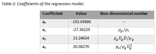
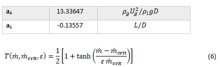
Where, 𝑝̃ is the non-dimensional shock pressure. The shock pressure was non-dimensionalized by the product of the gas density, hot-gas velocity, and the liquid speed of sound (𝜌𝑔𝑈𝑔𝑐𝑙). The exponents (ai) corresponding to the non-dimensional numbers (Π𝑖) and the regression model values are shown in Table 2. An exceptionally good fit was obtained for that data with a correlation of 98.5% and an average error of 3%. To account for the threshold effect around the critical mass flow rate the prediction of the linear regression is multiplied by a threshold function to get the final result. The threshold function is chosen to be based on the hyperbolic tangent function that takes the prediction to zero for mass flow rates below the critical mass flow rate.
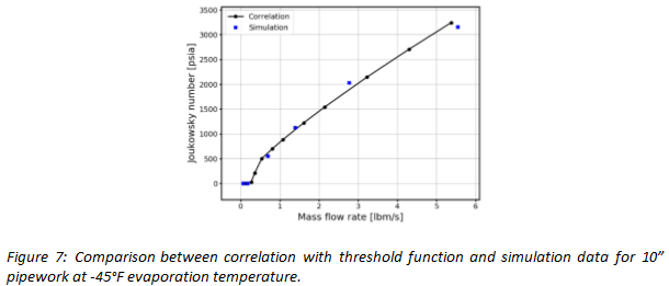
Where 𝜀=0.2, seems to give a good fit to the simulation data. The final form of the shock potential prediction for a 10” pipework at -45°F evaporation temperature is presented in Figure 7, showing a particularly good match to the simulation data.
The following inputs are required to use this correlation presented in Table 2,
- Diameter of pipe
- Evaporation temperature
- Hot gas mass flow rate
- Pipework length to diameter ratio
- Properties database such as Cool Prop (Bell, Wronski, Quoilin, & Lemort, 2014)
The correlation, applied to the available data from the 12” and 16” pipe diameters, gives predictions with an average error of 14% and a correlation of 93%. The correlation applied to the accident scenario simulated by Narayanan et al. (2021), which were comparable to the estimations from the forensic analysis by Wiencke (2008), also showed a very good match.
3.5 Application to hot-gas valve sizing
The correlation developed for different pipe sizes relating the hot gas mass flow to the resultant shock pressure amplitude is quite accurate with respect to simulation data. In each case there is a mass flow, somewhere between one half the critical mass flow and twice the critical mass flow, where slugs are not propagated and therefore no shocks are produced. At flow rates equal to twice the critical mass flow, the shock pressures were under 600 Psia for pipes 10” and smaller, with the stronger shocks occurring in the larger pipes. These shock pressures would not normally be considered strong enough to rupture non-brittle pipes. So, it is now established that there is a safety zone for sizing quick-opening hot gas solenoid valves centering on the critical mass flow.
Current hot gas valve sizing methodologies, as in Table A8 of the IIAR Refrigeration Piping Handbook (IIAR, 2004), do not take into consideration the shock-producing characteristics of the hot gas mass flows created when the hot gas valves open. Hot gas line and valve sizing is based on steady state operation at 2 or 5 psi pressure-drop across the valve. This does not represent the conditions existing when the valves open. There is a differential of around 100 psi across the valve and it will initially operate in a choked flow condition creating a surge of hot gas into the system. It is at this point when slug flow is most likely to be created, and shocks are most likely to occur. Maximum hot gas valve sizes should be established for this operating condition. After the initial surge, downstream pressures will rise, and the mass flows will decrease into the range below the critical mass flow.
It should be noted that the critical mass flows established in the study are quite low compared to current industry standards. Table A8 in the IIAR Refrigeration Handbook is based on hot gas flows of three times the equivalent refrigeration evaporator flows at a 2 or 5 psi pressure drop. Weincke (2008) reported on piping ruptures in a 320 TR freezer coil operating near –50°F suction temperature. The freezer was served by a 10” suction line and had a soft hot gas valve piping arrangement consisting of a ½” hot gas solenoid valve and a 2-1/2” hot gas solenoid valve. For a 10” suction line operating at -50°F the critical hot gas mass is 19.5 lbm/min. In Weincke (2008), the flow for the ½” hot gas valve was calculated at 14.16 lbm/min and for the 2-1/2” valve at 324 lbm/min. The ½” valve flow was below the critical mass flow, but it is also true, as stated in the report, that it did a poor job in pressurizing the system in the 2 minutes allowed, as set by the time clock. A ¾” valve might be estimated to have provided 32 lbm/min (based on the ratio of the port sizes of the two valves). 32 lbm/min is greater than the 19.5 lbm/min critical mass flow but less than 2 times the critical mass flow. There would have been no shock or only a light shock. The ¾” valve would have pressurized the system more quickly thereby reducing the flow through the 2-1/2” valve when it opened 2 minutes later.
According to the report the 2-1/2” valve produced a 324 lbm/min mass flow, well over the 19.5 lbm/min critical mass flow. The pipe rupture occurred when the 2-1/2” valve opened. Note that there was liquid in the system to create the slug because the liquid transfer system, designed to remove the liquid, was not operational at the time of the incident. For 19.5 lbm/min mass flow, Table A8 in the IIAR Refrigeration Piping Handbook would recommend a “Hot Gas Defrost Line Capacity” of 1-1/4” for a pressure drop between 2 and 5 psi. This is obviously well below customary practice in the field.
These examples are provided to demonstrate that, as a result of the findings in this study, methodologies for sizing hot gas valves need to be re-examined and improved. The sizing charts need to be updated accordingly.
4 Conclusions
This study focused on quantifying the possibility and magnitude of a hydraulic shock during the hot gas defrost of industrial ammonia refrigeration systems. The scenario considered the presence of a pre-formed slug that is driven into the pipework leading to the evaporation coil by the hot-gas flow. In contrast, earlier studies considered the condition where a slug is formed over a liquid layer due to the lift-up of liquid through the shear acting on the liquid surface by the hot-gas flow over it. The pre-formed slug scenario is considered a more severe condition due to a higher shock potential. The hot-gas mass flow rate required for the gas shear to scoop up liquid and form a slug is higher than the critical mass flow rate required to transport a pre-formed slug through the pipework. Additionally, the shear-induced slug achieves a lower speed as it travels over a thick stagnant liquid layer as compared to a pre-formed slug that moves over a thin liquid layer.
Through a careful preliminary study to determine the pipework length and pre-formed slug length, the pipework length used for the parametric study conducted was 100D along with a slug length of 10D. In this study, it was also found that a pre-formed slug in a dry pipe does not have sufficient condensation potential and will not form a hydraulic shock for long-enough pipes (> 50D). Therefore, all simulations were performed with a thin liquid layer of 0.2D height in the test section. A phenomenological model based on a densimetric Froude number was used to propose an estimate of a critical mass flow rate below which a pre-formed slug would collapse under the influence of gravity and not result in a hydraulic shock. The parametric study considered diameters from 1” to 16”, three evaporation temperatures of -45°F, -30°F, and -20°F and mass flow rates going from 1/6th to 16 times the critical mass flow rate of slug transportation.
Using the results of the parametric study, in particular the slug Joukowsky number for each case, a linear regression model (and a machine learning model) with high accuracy and correlation to the simulation results was developed. This correlation generated using the 1” to 10” pipe diameter data was successfully validated for the 12” and 16” diameter case. It was also able to successfully predict the accident scenario studied by Wiencke (2008). This correlation can be used to set the maximum size of a quick-opening hot-gas valve for a given suction pipe diameter and evaporation temperature by looking at the shock potential for a chosen hot-gas valve size (or hot-gas mass flow rate).
Currently hot gas valves are sized based on the evaporator size and operating temperature along with a 2–5 psi pressure drop across the valve. No consideration is given for the initial surge of the hot gas through the valve when the upstream pressure is approximately 100psi and the downstream pressure is around or below 0 Psig for low temperature refrigeration systems. At the time of opening, the hot gas valve will operate in a choked flow condition. The surge can accelerate any trapped liquid in the downstream piping and create a slug. The study shows that there is a mass flow range, within and below which a slug cannot be created or be sustained if it is created. Flows at least two times above this critical mass flow rate limit will produce shocks of various amplitudes for the suction pipe sizes shown and should be avoided. It should also be noted that for soft hot gas piping arrangements, the first valve to open should be sized close to the critical mass flow so that there is enough hot gas mass flow to raise the downstream pressure but not enough to create a shock. As the downstream pressure is increased, the pressure drop across the valve will be reduced and the flow will go down. Taking note of the critical mass flow, the second valve can be sized larger because the pressure-drop across it will be lower. Additionally, it should be noted that since the second-to-open valve is larger, it should not be energized until it is determined that the pressure drop across the valve has been reduced, thereby reducing the risk that flows through the valve would exceed the critical mass flow values.
References
AFRY Switzerland. (2020). TransAT User Manual. Retrieved from www.transat-cfd.com.
Bell, I., Wronski, J., Quoilin, S., & Lemort, V. (2014). Pure and pseudo-pure fluid thermophysical property evaluation and the open-source thermophysical property library CoolProp. Industrial & engineering chemistry research, 53(6), 2498-2508.
IIAR. (2004). Ammonia Refrigeration Piping Handbook. International Institute of Ammonia.
Labois, M., & Narayanan, C. (2017). Non-conservative pressure-based compressible formulation for multiphase flows with heat and mass transfer. International Journal of Multiphase Flow, 96, 24-33.
Martin, C., Brown, R., & Brown, J. (2007). Condensation-Induced Hydraulic Shock, Final Report, Tech. Rep ASHRAE 970-RP. ASHRAE.
Narayanan, C. (2022). CFD-based design basis for the avoidance of hydraulic shock in ammonia pipework systems. (p. Technical Paper #1). Savannah, Georgia: IIAR Technical Papers.
Narayanan, C., Thomas, S., & Lakehal, D. (2020). CFD Study of Hydraulic Shock in Two-Phase Anhydrous Ammonia. ASHRAE Transactions, 126.2.
Narayanan, C., Wiencke, B., & Loyko, L. (2021). CFD Analysis of Pipework Fracture due to Hydraulic Shock in an Ammonia Refrigeration System. IIAR Natural Refrigeration Conference & Expo. Palm Springs, CA, USA: IIAR.
Wiencke, B. (2008). A Case Study of Pipework Fracture due to Hydraulic Shock in an Ammonia System. IIAR Ammonia Refrigeration Conference & Exhibition. Technical Paper #6. Colorado Springs, Colorado, USA: IIAR.